| |
 Active Active
Une des dex sources de triangulation est projetée
On ajoute un laser ou un projecteur

 Triangulation (Short Range) Triangulation (Short Range)
Mesure l'angle d'incidence entre le faisceau envoyé et le photorécepteur
- Scan pattern
- Image 2D ordinateur / Fringe pattern
-
 InSpeck
http://www.inspeck.com/ InSpeck
http://www.inspeck.com/
Pour nous rejoindre
Siège Social
3530, boul. Saint-Laurent,
Suite 503
Montréal (Québec)
CANADA H2X 2V1
Tel.: 514.284.1101
Fax: 514.284.1108
Centre de développement de produit
1400, Blvd. Du Parc-Technologique
Suite 200
Québec (Québec)
CANADA G1P 4R7
Tel.: 418.682.6161
Fax: 418.682.3884
===============================================================
in Speck,
1994.
WWW Version. Vendor, Range Sensor. 3-D data. Not a laser scanner. Scanned human models.
----------------
WELCOME TO THE INSPECK PRODUCT FAMILY!
3D Photo Crystal Booth: Always at the cutting edge of 3D technology, InSpeck is at it again with
an revolutionary new product called the 3D Photo-Crystal Booth...
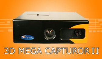
3D Mega Capturor II:
CYCLOPS²: Introducing CYCLOPS², the next stage in 3D camera evolution for 3D crystal
engraving...
The 3D Mega Capturor II is InSpeck's professional digitizing solution that offers higher texture
resolution and 3D geometry...
InSpeck Software: At the heart of all our hardware is our award winning software...
» See document: http://www.inspeck.com/
- Surtout spécialisé dans la capture
d'apparence 3D avec texture de personnes
- 3D Photo Crystal Booth
- 3D stereo portraits (holographique)
- Application médicales / Ésthétique
- 3D Mega Capturor II
The 3D Mega Capturor II is InSpeck's professional digitizing solution that offers higher texture
resolution and 3D geometry...
- 3D Mega Capturor DF
3D Mega Capturor DF SF LF
CV (à la référence) 455x355 895x715
PCV 350 750
Résolution en X 0.4 0.7
Résolution en Y 0.4 0.7
Distance Min. 950 800
Distance de ref. (Z=0) 1100 1100
Texture (pixels) 1280x1024 1280x1024
Géométrie (pts) 1.3M 1.3M
Temps acqu. (sec) 0.7 0.7
PC configuration P4 + 512M RAM P4 + 512M RAM
Système d'exploitation WIN 2000/XP WIN 2000/XP
Toutes les unités sont en millimètres (mm) sauf si spécifié autrement.
Les valeurs nominales peuvent variées de +/- 5%.
- Cyclops
- CYCLOPS 2
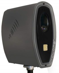
LÉVOLUTION A UN NOM: CYCLOPS²
Voici le CYCLOPS², la nouvelle étape évolutive du développement de caméras 3D pour la gravure
dans le cristal. Cette caméra est entièrement automatique et génère un nuage de points prêt à être
engravé en quelques secondes seulement. CYCLOPS² est très rapide et si facile à utiliser
quaucune formation nest nécessaire. Si vous êtes entrepreneur, InSpeck peut vous aider à
démarrer votre propre commerce de gravure 3D dans le cristal dans le cristal et de Portraits Stéréo
3D. Malgré son prix déjà fort attrayant, le CYCLOPS² vient quand même avec son propre logiciel
dapplication ainsi quune caisse de transport.
=======================
InSpeck Cyclops²
Le CYCLOPS² est une version évoluée du Cyclops, caméra vedette
dInSpeck de première génération. Cette nouvelle génération de caméra
3D compte plusieurs améliorations ce qui fait du CYCLOPS² le meilleur
outil jamais vu pour lapplication de gravure 3D dans le cristal (SSLE). Si
vous êtes un entrepreneur désirant démarrer votre propre entreprise de
gravure 3D dans le cristal (SSLE) et/ou de 3D Stéréo Portraits (3DSP),
InSpeck peut vous fournir équipement et expertise pour atteindre vos
objectifs.
Nous disions donc que le CYCLOPS² est plus avancé que son
prédécesseur, le Cyclops. La principale raison est que sa caméra interne
offre une texture plus de deux fois supérieure et améliore beaucoup la
géométrie 3D. Avec le CYCLOPS², vous pouvez numériser une ou deux
personnes en même temps et ainsi que numériser les cheveux humains
sans problème. Cette caméra vient aussi avec sa propre base de soutient
ce qui vous permettra de la mettre debout sur une table sans avoir
recours à un trépied.
En plus de toutes ces améliorations, le CYCLOPS² demeure une caméra
entièrement automatisée, très rapide vendu à un prix très compétitif. Le
CYCLOPS² est si facile dutilisation quune formation nest pas nécessaire ;
le manuel ainsi quun accès t/l/phonique/Internet à notre département
technique suffiront à vous guider.
Voici les avantages principaux du CYCLOPS²:
Automatique: Le CYCLOPS² est complètement automatisé. Soyez prêts à
engraver en quelques secondes seulement.
Logiciel inclus: Le CYCLOPS² vient avec PCS, un logiciel vous permettant
de numériser vos sujets. PCS offre un choix limité de cristaux, lesquels
vous pourrez engraver.
Novices bienvenus: Aucune expérience nest nécessaire pour opérer le
CYCLOPS².
Base incluse: Le CYCLOPS² vient avec une base de soutient qui lui permet
de rester à la vertical sans avoir à utiliser un trépied traditionnel.
Rapidité et portabilité: Une fraction de seconde et le tour est joué! Cest
tout ce qui est nécessaire pour prendre une photo 3D. Non seulement
cette caméra est très rapide mais elle aussi très portable grâce à sa petite
taille.
Flexibilité commerciale: Le CYCLOPS² sert pour lapplication SSLE mais
aussi pour celle des 3D Stéréo Portraits (3DSP).
Photo de groupe: Vous pourrez numériser 2 (et des fois 3) personnes en
une seule photos.
Prix abordable: InSpeck na jamais eut de numériseur plus abordable!
Cest à en faire frémir la compétition!
Pour plus dinformation sur ce produit, cliquez ici et veuillez compléter
le formulaire.
- Caméras 3D pour la gravure dans le cristal
- Http://www.inspeck.com/?langage=Fran%E7ais
» See document: http://www.inspeck.com/?langage=Fran%E7ais
- Fraction de seconde et le tour est joué
- 1 ou 2 Personnes en même temps et ainsi que
les cheveux humains
- Software
- Plusieurs "photos" requises pour faire un modèle 360degrés
-
Breuckmann
Http://www.breuckmann.com/
» See document: http://www.breuckmann.com/index.php?id=breuckmanngmbh&L=2
- Stereo active
-
Patented MPT projection unit
- Fringe projection
- Ressemble à des wavelets carrées
- Arbre de résolution, arêtes en multirésolution
- 2 caméras
- Plusieurs images = 1 vue 3D
- Besoin d'un tracker externe pour scanner les plus gros objets (voitures)
- Matériaux fibre de carbone plus rigide et léger pour éviter les déformations
- Products
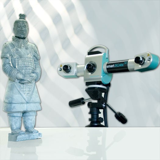
- * stereoSCAN 3D
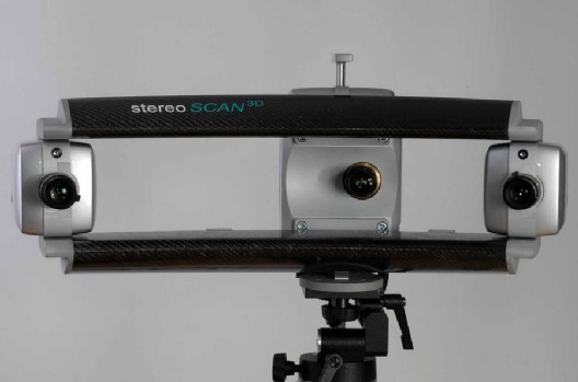 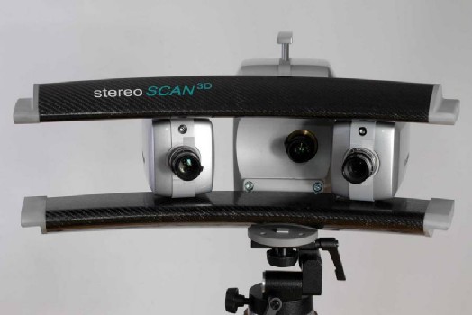
stereoSCAN 3D - The Measuring System for Highest Demands
Maximum Flexibility and Accuracy
The stereoSCAN3D system was developed to meet the increasing demands of our customers.
stereoSCAN3D consists of a fully integrated combination of our patented MPT projection unit and 2
high resolution digital cameras which are asymmetrically positioned at either side of the projector.
This configuration enables maximum performance with regard to flexibility and precision.
Flexibility:
* Due to the asymmetrical camera set-up, three different triangulation angles
(10°, 20° and 30°)
are implemented. By this way, even areas which are otherwise difficult to capture, can be reliably
assessed.
* Easily exchangeable objectives ensure fast switching between different measurement
areas.
* Camera modules may be mounted fast and easily in various positions on the
sensor base.
With such flexibility, even small measurement areas can be realized without substituting the
sensor base.
Precision:
* Two digital cameras featuring 1.4 million pixels each (optionally: 6.6 mega
pixels) guarantee
highest resolution and accuracy.
* The carbon fibre base structure ensures optimum mechanical and thermal stability
of the
sensor.
* The software provides intelligent data management procedures based on quality
criteria,
resulting in a
high degree of data certainty.
* Due to the fast acquisition time of approx. 1 second, the occurrence of negative
external
influences is minimized.
* Calibration may be performed by the user within minutes and with a high degree
of accuracy.
* The system is certified VDI/VDE 2634.
- 2x 1.4Mpixels dig camera (optionally: 6.6Mpixels)
- 1s acquisition time
- * naviSCAN 3D

INNOVATIVE SCANNING FOR MORE THAN TWO DECADES
fast -accurate -reliable
These are the identifying words for the today´s production development and
optimization, quality assurance and inspection, reverse engineering and rapid
prototyping. To comply with these requirements, optical metrologies have been
developed and adapted to digitize and measure even smallest 3D structures with HighDefinition.
For more than two decades Breuckmann and Metronor both have been an innovative outriders and
leader in system development and product manufacturing. With our
diversified product spectrum we cover a wide range of technical applications such as reverse
engineering, inspection, rapid prototyping, design, surface inspection and many others. The unique
configuration of the stereoSCAN3D enables maximum performance
with regard to flexibility and precision. The latest development is now our naviSCAN3D.
The combination of a Metronor duo portable CMM and a breuckmann stereoSCAN3D
white-light scanning system offers unknown flexibility and accuracy to users of
portable measurement equipment. Scanning and Probing has never been so easy
and allows sophisticated measuring and inspection tasks on the shop floor.
While the Metronor duo system sets up a large working volume, the stereoSCAN3D precisely and
quickly scans areas up to one square meter per shot. Stitching several shots works seamlessly
and without any user interaction through the navigation target thats mounted to the back of the
scanner. This navigation target allows complete freedom for any movement and position of the
scanner. During the scan sequence the system even monitors and notices any movement of
scanner or part, thereby assuring precise measurement and scans.
The ideal solution for inspection and reverse engineering
tasks on large components even under demanding industrial
conditions. See the difference in quality, speed and robustness!
Benefits
* Probing and Scanning works seamlessly in
the same coordinate system
* Large working volume
* No need to apply (and remove) targets or stickers
* Quick and straightforward workflow
* Easy to use and hence quick to learn
* Hidden points that are not accessible through the
scanner, can be measured with a touch probe
* Ideal combination for applications that require discrete
point probing as well as high density scan data
* System is completely portable, with heavy duty
flight cases
* Can be used in hostile shop floor environments
* System monitors vibrations and checks accuracy online
Applications
* Inspection tasks on large components under shop
floor conditions
* Reverse engineering
* Scanning models for Rapid Prototyping
* Any application that requires a portable CMM
and high quality and high density scan data
Wyman Gordon in Worcester, MA, USA is a major supplier
of forgings to both military and commercial aerospace manufacturers. They are using the system
for first-article as well as reverse engineering /shape verification of old tooling. There are several
challenges to obtain highly accurate data in a hostile forging shop: this includes large components
(up to 27 ft, 9 m long) and hot dies.
- StereoScan 3D
- + Vicon tracker w 2 cameras
- Larger volumes
- * smartSCAN 3D
- * optoTOP-HE

The high resolution digitising system optoTOP-HE is the result of consistent development of our
well-established optoTOP system which has, over the last 15 years, become one of the most
successful topometric measuring systems worldwide.
* Flexibility
The range of standard measuring areas has been further extended.
The system is available with three standard sensor bases covering diagonals from 50 mm to 775
mm.
Additional tele lenses and wide-angle lenses enable measurement areas between 30 and 1050 mm
(diagonal). Furthermore, customised sensor configurations ranging from a few mm² to approx. 5 m²
can be offered on request.
All measurement areas can be simply and rapidly adjusted by exchanging either the objective or
the sensor base. At a weight of only 2 kg, the sensor can easily be mounted onto positioning
systems, such as robots and CMMs.
* Fast Data Acquisition
The patented MPT projection unit enables extremely rapid data acquisition within approximately
one second.
* Precision
A carbon fibre base structure ensures optimum mechanical and thermal stability of the
sensor.Calibration may be performed by the user within minutes, ensuring a high degree of
accuracy at all times.
* High Resolution
Featuring 1.4 mega pixels (optionally 6.6 mega pixels) and a digital zoom, the digital camera
provides maximum resolution.
- Telelenses
- Larger volume / single view
- * optoSCAN
- * µikroTOP
- * dermaTOP
- * faceSCAN
- * bodySCAN
- * triTOS
- * services
- * LogIn
- Félix Rochette et Patrick Hébert 2005-
- Zèbres
- Sinus
- Pas de couleur
- Peirong Jia et P. Hébert 2006-2007
- Essaye d'avoir de la couleur
- Http://ieeexplore.ieee.org/stamp/stamp.jsp?arnumber=01545121
» See document: http://ieeexplore.ieee.org/stamp/stamp.jsp?arnumber=01545121
- Crosshair X
-
 Creaform 3D
http://www.creaform3d.com/en/handyscan3d/ Creaform 3D
http://www.creaform3d.com/en/handyscan3d/
» See document: http://www.creaform3d.com/en/handyscan3d/
- Handyscan
- Tubic, Hébert et al (2000-)
- 2 caméras + laser (fixes)
- Capteur tenu en main
- Déplacements requis
- Auto-Positionnement requis
- Marqueurs passifs
- Ruban 3M
- Éclairage confondu avec la caméra
- Mise en registre
-
 Intégration avec autres senseurs de position Intégration avec autres senseurs de position
- Trajectoire random
- Products
3D scanners are often used for modeling three dimensional models which may be used for a future
3D rendering. 3D scanners from the Handyscan 3D line-up are self-positioning truly portable
handheld laser scanners that boast the latest technological innovations and offer powerful and
efficient functionalities.
Our 3D scanners have been designed to maximize your needs while fitting with your current
budget. If you are looking for easy-to-use laser scanners, please select a 3D laser scanner below.
REVscan
REVscan 3D ScannerThe REVscan 3D scanner is the first self-positioning and truly portable laser
scanner developed by Creaform.
Learn more about the REVscan 3D Scanner arrow
EXAscan
EXAscan 3D ScannerThe EXAscan 3D scanner is the most flexible, freeform inspection device on
the laser scanner market.
Learn more about the EXAscan 3D Scanner arrow
VIUscan
VIUscan 3D ScannerThe VIUscan is the only truly portable handheld 3D color scanner to deliver
such accurate and hyperrealistic 3D scanning results.
Learn more about the VIUscan 3D Scanner arrow
MAXscan
MAXscanThe MAXscan self-positioning and handheld 3D laser scanner from the Handyscan 3D line-up was
designed especially for 3D scanning and inspection of large and very large parts.
Learn more about the MAXscan 3D laser scanner. arrow
ERGOscan
ERGOscan 3D ScannerThe ERGOscan is the scanner from the Handyscan 3D line-up that was
developed especially for medical applications.
Learn more about the ERGOscan 3D Scanner arrow
If you are not sure about which 3D scanner to choose, click on the Learn more about link beside
every 3D scanner image above.
How do 3D scanners work?
3D laser scanners send trillions of light photons toward an object and only receive a small
percentage of those photons back via the optics that they use. With that technique, 3D scanners
can build a 3D modeling object very quickly. 3D scanners produce a picture describing the
distance information of each point to an object. Moreover, the 3D scanner photons probes the
object surface at the speed of light.
Why use 3D scanners?
3D scanners are usually used to acquire the x, y and z coordinates of millions of points of an
object and directly generate a polygonal mesh of the part to recreate it in 3D. 3D scanners help
understanding complex forms or presenting a visual conception of your work. With the 3D models
produced by the 3D scanners, you can reproduce or trace shapes fast. 3D scanners are widely
used in the automotive and aerospace industries, and also in the entertainment industry to
digitalize 3D models for movies and video games, for example. Plus, 3D scanners are more and
more used in orthotics to capture a 3D shape of the patients.
- REVscan

- Basic / original
- Weight 980 grams (2.1 lb)
- Dimensions 160 x 260 x 210 mm (6.25 x 10.2 x 8.2 in)
- Measurements 18,000 measures/s
- Laser Class II (eye-safe)
- Resolution in z axis 0.1 mm (0.004 in)
- Accuracy Up to 50 µm (0.002 in)
- ISO 20µm + 0.2 L /1000
- EXAscan

- Freeform
- Weight 1.25 kg (2.75 lb)
- Dimensions 172 x 260 x 216 mm (6.75 x 10.2 x 8.5 in)
-
Measurements 25,000 measures/s
- Laser Class II (eye-safe)
- Resolution in x, y, z axis 0.05 mm (0.002 in)
- Accuracy Up to 40 µm (0.0016 in)
- ISO 20µm + 0.1 L /1000
- Depth of field 30 cm (12 in)
- VIUscan
VIUscan
VIUscan 3D ScannerThe VIUscan is the only truly portable handheld 3D color scanner to deliver
such accurate and hyperrealistic 3D scanning results.

- Color
- Texture Resolution 50 to 250 DPI (user-configurable)
- Texture Color 24 bits, sRGB-calibrated
- Weight 1.3 kg (2.85 lb)
- Dimensions 172 x 260 x 216 mm (6.75 x
10.2 x 8.5 in)
- Measurements 18,000 measures/s
- Laser Class II (eye safe)
- Geometry Resolution 0.1 mm (0.004 in)
- Accuracy Up to 50 µm (0.002 in)
- ISO 20µm + 0.2 L /1000
- Depth of field 30 cm (12 in)
- Output file formats .dae, .obj, .ma, .ply, .stl, .txt,
.wrl, .x3d, .x3dz, .zpr
- MAXscan
MAXscan

MAXscanThe MAXscan self-positioning and handheld 3D laser scanner from the Handyscan 3D line-up was
designed especially for 3D scanning and inspection of large and very large parts.
- Large parts
- Weight 1,27 kg (2.80 lbs)
- Dimensions 172 x 260 x 216 mm
- (6.75 x 10.2 x 8.5 in)
- Measurements 18,000 measures/s
- Laser class II (eye safe)
- Resolution in Z axis 0.1 mm (0.004 in)
- Accuracy Up to 50 µm (0.002 in)
- ISO 20 µm + 25 µm/m
- Depth of field (scan) 30 cm (12 in)
- Output format files .dae, .fbx, .ma, .obj, .ply, .stl, .txt, .wrl, .x3d, .x3dz, .zpr
- ERGOscan

The ERGOscan is the scanner from the Handyscan 3D line-up that was developed especially for
medical applications.
- Medical
- 980g
- Accuracy - Up to 0.5 mm (0.02 in) on a 500 mm (20 in) volume
-
Class I laser Eye Safe
- Taux vidéo
- 3D Digital
Http://www.3ddigitalcorp.com/index.shtml
3D Digital (now own rights to RealScan 3D... which was previously owned by Intel, and before that
Lockheed Martin). The Model 100 portable scanner has a USB interface for easy interfacing but no
color texture. The Model 200 has color texture.
===================================
The Best in 3D Scanner Technology
3D Digital Corporation personnel have over five decades of combined work experience
in the 3-Dimensional Scanning industry with more than half of that experience in the 3d scanning field.
3DD
has witnessed the rise of this amazing technology and continues to grow and mature along with
the industry. 3D Digital has proven many times over that our 3D scanner hardware and software
reside among the most elite in providing solutions for everyday real world applications.
This experience gives us a keen insight into what the end user needs and relies
on for their 3D
scanning tools. We also have had to face the same shortcomings and inadequate performances
endured when using other products. Keeping these things in mind, 3D Digital has set out to
revolutionize the 3D scanning process by providing the hardware and software that are not only
easy to use with time saving efficiency but also immensely accurate and productive as well.
Learn more about 3D Laser Scanner technology.
» See document: http://www.3ddigitalcorp.com/index.shtml
- E-Scan
Http://www.escan3d.com/
- Http://www.3ddigitalcorp.com/Products/escan.shtml
» See document: http://www.3ddigitalcorp.com/Products/escan.shtml
-
 7345 US$ 7345 US$
- E-Scan
Http://www.escan3d.com/?gclid=CN7lm6XF9ZgCFQEoGgodVGph1w
EScan Software
If you would like detailed information on the eScan, please visit the official eScan Website.
Specifications
Resolution
0.005" @ 12"
0.008" @ 26"
Primary Application
Medium Range Scanning
Medium Size Objects
135 microns @ 300 mm
210 microns @ 650 mm
Standard Deviation from ideal scanning plane
+/-0.006" @12"
+/-0.010" @ 26"
Field of View
40 degrees
+/-150 microns @ 300mm
+/-250 microns @ 500mm
Depth of Field
12-26" / 300-650mm
Lens
Manual Lens
Point Density
255 x 1000
Parallax Base length
4.33" (110mm)
Dimensions
210x245x120mm
(8.3x9.6x4.7)
Weight 5.3 lbs / 2.4kg
Export formats
STL, OBJ, ASCII
(0.001" =25 microns) Specifications subject to change without notice
EScan Software Features
* Merges and Aligns multiple Scans together
* 3D Viewer
* Color and Appearance Adjustments
* Scaling and basic Measuring
* Export point cloud and mesh formats
Applications
* Reverse Engineering
* Orthotics - Click here for more Info on clinical use
* Design
* Animation
* Footwear
* Artisan
* Virtually any type of 3D modeling
Pricing
EScan pricing is set at $7,345 including software for registration and processing, making it an
affordable solution for your 3D scanning needs.
What is included;
* EScan
* Power and USB cables
* Software - Scanning operation + Alignment + editing tools
* 1 year limited warranty
Additional custom options, such as software tailored to user's applications, are available. Please
contact us directly for information regarding OEM contracts and special licensing agreements.
» See document: http://www.escan3d.com/?gclid=CN7lm6XF9ZgCFQEoGgodVGph1w
- Optix 400
» See document: http://www.3ddigitalcorp.com/Products/optix.shtml
- 7 seconds per scan
- Color texture option which captures true 7MP color images and overlays the information over the point cloud
- Own rights to RealScan 3D
3D Digital (now own rights to RealScan 3D... which was previously owned by Intel, and before that
Lockheed Martin). The Model 100 portable scanner has a USB interface for easy interfacing but no
color texture. The Model 200 has color texture.
- Intel
- Lockheed Martin
- Model 100 portable scanner has a USB interface for
easy interfacing but no color texture
- Model 200 has color texture
- Scan line
-
 Sick IVP
Http://www.sickivp.se/sickivp/en.html Sick IVP
Http://www.sickivp.se/sickivp/en.html
SICK IVP - Your partner in Machine Vision!
SICK IVP provides industrial vision cameras for factory automation. The product line includes
Vision Sensors, Smart Cameras and cameras for high speed 3D machine vision. Target customers
are OEM machine builders, system integrators and large end-users.
Since June 2003, SICK IVP is a subsidiary to the multinational German corporation SICK AG with
4,000 employees that are active in the SICK Group worldwide. With more than 40 subsidiaries in
over 20 countries, numerous agencies and several affiliated companies, SICK is one of the leading
producers of sensors and sensor solutions.
» See document: http://www.sickivp.se/sickivp/en.html
- Industrial Cameras
- Ranger

Advertisement in Vision Systems Design
Ranger: Fastest 3D Available!
Ranger is the ultimate 3D camera for the most advanced needs. With its extreme speed, high-quality 3D
data and Camera Link or Gigabit Ethernet interface, it can be used to solve almost any
in-line application where true three dimensional shape is essential for success.
==================
* Performance: Up to 35,000 3D profiles per second
* Interface: CameraLink or Gigabit Ethernet
* Development platform: C++ (VS .NET 2003) or C (VS .NET 2003, VS6) for all
cameras
* Evaluation Software: Ranger Studio (requires Windows XP Professional)
* Synchronization of data: Free running, light switch enable, rotary encoder
trig for all cameras
* Camera Size (L X H x D): 110 x 50 x 50 mm or 125 x 52 x 52 mm
* Power: 24V DC
* Options: IR filter for increased robustness to ambient light disturbances
==================
Ranger - The fastest camera in the world for three dimensional shape measurement!
The Ranger camera measures 3D features at unmatched speed producing a complete data set of
the object measured. Providing a 3rd dimension adds height and shape measurement data, which
can be critical when correctly classifying an object. Ranger is the key component in many market
leading in-line inspection machines used in the Electronic, Semicon, Wood, Robot Vision, Plastic,
Rubber and Food industries.
The fastest 3D available!
The Ranger acquires up to 35,000 profiles per second, each containing up to 1536 high quality 3D
coordinates. This is more than 45 million 3D points per second!
Image processing handled by the camera
The complete 3D calculation is done inside the camera and the ready-to-use 3D coordinates are
sent directly to a standard PC via CameraLink or Gigabit Ethernet. This eliminates the need for
expensive post processors.
Easy to integrate
The 3D data is represented in the PC memory as a line scan intensity data stream, except that the
pixel value corresponds to height instead of greyscale. This enables the data to be evaluated by
your own or commercially available machine vision software. Any 3d party vision software with a
C/C++ programming interface (such as MIL, HALCON, Sapera, etc) can be used. The HALCON
software also offers a native Ranger interface which facilitates solution building for instance by
using their graphical and interactive prototyping environment HDevelop. For easy integration of
Ranger into LabVIEW a dedicated Ranger toolkit is available. More information can be found on the
support pages.
Best market price/performance
Maximized performance without the need for super performing post processors, easily integrated
with 2D machine vision software, allows you to quickly develop competitive solutions, both from
performance and cost point of view!
Ranger C
High speed 3D and MultiScan camera with CameraLink interface. Up to 30,000 profiles/s in 3D
mode. Several 3D algorithms and MultiScan components available. Highly configurable via software
parameters. I/O and encoder inputs at TTL level.
Ranger E
High speed 3D and MultiScan camera with GigaBit Ethernet interface. Up to 35,000 profiles/s in 3D
mode. Several 3D algorithms and MultiScan components available. Highly configurable via software
parameters. 24V I/O and RS422 (TTL level) for encoder input.
Ranger D
Pure 3D camera with Gigabit Ethernet interface with mid speed performance of 1,000 profiles/s.
Uses a high precision 3D algorithm with few parameters. No MultiScan functionality. 24V I/O and
RS422 (TTL level) for encoder input.
* Performance: Up to 35,000 3D profiles per second
* Interface: CameraLink or Gigabit Ethernet
* Development platform: C++ (VS .NET 2003) or C (VS .NET 2003, VS6) for all
cameras
* Evaluation Software: Ranger Studio (requires Windows XP Professional)
* Synchronization of data: Free running, light switch enable, rotary encoder
trig for all cameras
* Camera Size (L X H x D): 110 x 50 x 50 mm or 125 x 52 x 52 mm
* Power: 24V DC
* Options: IR filter for increased robustness to ambient light disturbances
- 3D camera
- Triangulation Ligne Laser + Balayage 1
direction (Line scan 3D)
- Plan laser
- Image processing handled by the camera
- Pixel value corresponds to height instead of
greyscale
- Multiscan
- CL or GigE
- CL
- Ranger C
High speed 3D and MultiScan camera with CameraLink interface. Up to 30,000 profiles/s in 3D
mode. Several 3D algorithms and MultiScan components available. Highly configurable via software
parameters. I/O and encoder inputs at TTL level.
- Cameralink
- Multiscan
- 30,000 profiles/s in 3D mode
- GigE
- Ranger E
Ranger E
High speed 3D and MultiScan camera with GigaBit Ethernet interface. Up to 35,000 profiles/s in 3D
mode. Several 3D algorithms and MultiScan components available. Highly configurable via software
parameters. 24V I/O and RS422 (TTL level) for encoder input.
- Ranger D
Ranger D
Pure 3D camera with Gigabit Ethernet interface with mid speed performance of 1,000 profiles/s.
Uses a high precision 3D algorithm with few parameters. No MultiScan functionality. 24V I/O and
RS422 (TTL level) for encoder input.
- Gigabit Ethernet
- Mid speed performance of 1,000 profiles/s
- No MultiScan functionality
- 24V DC
- Options: IR filter for increased robustness to ambient light disturbances
- 35,000 profiles per second, each containing up to
1536 high quality 3D coordinates
This is more than 45 million 3D points per second!
-
 This is more than 45 million 3D points per second! This is more than 45 million 3D points per second!
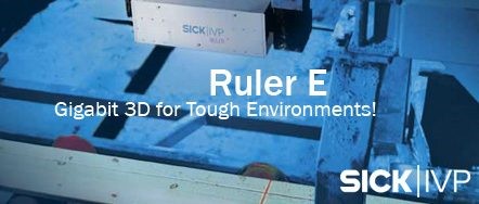
- Ruler E
http://www.sickivp.se/sickivp/products/3d_cameras/ruler/en.html
===============================================================
Ruler E - Gigabit 3D for Tough Environments!
A complete new generation of Ruler is here - more than four times faster and with three times
higher resolution than the previous generation. Now with ultra fast Gigabit Ethernet interface!
Ruler E is the solution for demanding 3D applications in any production line. It is designed to
measure anything from logs in a sawmill to cars in the automotive Industry. Ruler E is intended for
tough environment with a shield level of IP65.
Ruler E contains a laser and Image sensor assembled in fixed positions. It is calibrated before
delivery to give you high quality 3D data. This in combination with .Net assembly technology gives
you short development time and cost effective solutions.
===============================================================
A complete new generation of Ruler is here - more than four times faster and with three times
higher resolution than the previous generation. Now with ultra fast Gigabit Ethernet interface!
Ruler E is the solution for demanding 3D applications in any production line. It is designed to
measure anything from logs in a sawmill to cars in the automotive Industry. Ruler E is intended for
tough environment with a shield level of IP65.
Ruler E contains a laser and Image sensor assembled in fixed positions. It is calibrated before
delivery to give you high quality 3D data. This in combination with .Net assembly technology gives
you short development time and cost effective solutions.
* Performance: 10.000 3D profiles per second
* Interface: Gigabit Ethernet
* Host platform: PC, Windows XP
* Development environment: Net Assembly or C++ (VS .NET 2003)
* Synchronisation of data: Free running, light switch enable, rotary encoder
trig
* Dimensions (LxHxD): 420x163x105 mm
* Enclosure rating : IP 65
* Laser class: 2M/2 (optionally 3B)
* Options: Scatter measurement, 3B laser, Heating
Max profile width
Ruler E1200: 1024
Ruler E600: 1536
3D height resolution
Ruler E1200: 0.4 mm
Ruler E600: 0.2 mm
Example field of view
Ruler E1200: 250x1200 mm
Ruler E600: 250x600 mm
» See document: http://www.sickivp.se/sickivp/products/3d_cameras/ruler/en.html
- GigE
- 10.000 3D profiles per second
- Photo

- Factory Calibrated
- Vision Sensors
http://www.sickivp.se/sickivp/products/vision_sensors/en.html
» See document: http://www.sickivp.se/sickivp/products/vision_sensors/en.html
- Caméra fixe, objet en mouvement
- Tapis roulant
- Trajectoire continue ou droite
- Synchro mécanique
-
DAVID Software
http://www.david-laserscanner.com/
http://www.david-laserscanner.com/
DAVID Vision Systems GmbH
Rudolf-Diesel-Str.2a
56070 Koblenz, Germany
s [dot] winkelbach [at] david-laserscanner [dot] com
Anbieter im Sinne des §6 TDG:
Picotronic GmbH
HRB20026 - Amtsgericht Koblenz
Rudolf-Diesel-Str.2a 5
D-56070 Koblenz,Germany
Tel. +49 (0)261/983497-70
Fax. +49 (0)261/983497-77
info [at] picotronic [dot] de
================
http://www.engadget.com/2006/12/22/david-software-turns-your-webcam-into-a-3d-laser-scanner/
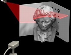
DAVID software turns your webcam into a 3D laser scanner
by Darren Murph, posted Dec 22nd 2006 at 5:09PM
Those snazzy laser-based scanners that just have to make at least one appearance in every
science-fiction film worth its salt are now available for your home, and it'll cost you quite a bit
less
than what Hollywood presumably shelled out for theirs. Thanks to folks who see value in "free,"
a
few clever programmers have crafted the DAVID Laserscanner software, which turns your webcam
into an ultra-sensative laser recorder and then reconstructs the object on-screen based on the
breaks in the beam. Reportedly, all your need is a PC, a halfway decent webcam, a perfect 90-degree
angle in the corner of your wall, some foreign object(s), and a street-corner laser pointer to
go along with the software. DAVID computes the beam length as you "brush over the object with
the laser" in order to render the object on your display, and while it can't quite do 360-degree
renditions just yet, the developers hope to add that functionality soon enough. So, if you're the
proud owner of all the above prerequisites, be sure to hit the read link and get your laser scanning
on.
» See document: http://www.david-laserscanner.com/
- Webcam
- Ligne Laser
- Il faut déplacer le laser
- 2 murs à 90 degrés
- Marqueurs passifs
- Marqueur géométrique (2 plans connus)
- Free SW
- Licenses SW
- Shop
Http://shop.david-vision-systems.de/
» See document: http://shop.david-vision-systems.de/
- Scan point
-
ServoRobot
St-Bruno, Québec
http://www.servorobot.com/
Servo-Robot Inc. (Headquarters)
1370 Hocquart, St-Bruno
Quebec, CANADA
J3V 6E1
Tel: +1 (450) 653-7868
Fax: +1 (450) 653-7869
Administration: info@servorobot.com
Sales and marketing: sales@servorobot.com
Technical service:service@servorobot.com
Purchasing: achats@servorobot.com
SRI Headquarters in St-Bruno, Qc, Canada
Servo-Robot USA
Servo-Robot Corp.
P.O. Box 069, Mequon
WI, 53092 U.S.A.
Tel: +1 262-238-4625
Fax: +1 262-238-4626
Contact
j.noruk@servorobot.com
d.sytkowski@servorobot.com
==============================
Servo-Robot was founded in 1983. Our world headquarters, R&D center and production plant are
located in the St-Bruno Industrial Park, south of Montreal, Quebec, in Canada. Servo-Robot has a
well established network of subsidiaries and distributors around the world.
For more than 25 years, Servo-Robot has been producing robotic laser vision and sensing systems
for welding and robotic and automated manufacturing. In particular, Servo-Robot is the recognized
leader in the performance improvement of joining processes such as laser seam tracking, laser
seam searching, weld inspection through our unique3-D laser vision technology. Innovation and
practical manufacturing process knowledge is the key to the availability of our wide product line
covering various areas in intelligent manufacturing.
==============================
``Servo-Robot manufactures standard and custom laser range finders and 3D laser vision systems
for various applications, particularly process management and robotics. Our engineering team
develops specific software, machine vision systems, powerful 3D image processors using most up-to-date
parallel DSP technology, for various applications to meet customer needs.''
=============
http://news.thomasnet.com/fullstory/553709
Company Information:
Name: Servo-Robot Corp.
Address: 1370 Hocquart
City: Bruno
State: QC
ZIP: J3V6E1
Country: USA
Phone: 450-653-7868
FAX: 450-653-7869
http://www.servorobot.com
==================
» See document: http://www.servorobot.com/
- Vision pour des robots industriels
- Autosynchronisé
- Robots soudeurs
- Jupiter (LVSN 1990s)
- Quanta
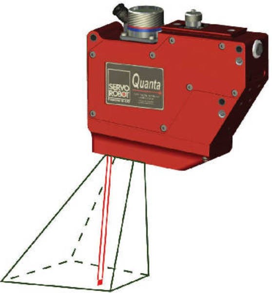
New from Servo-Robot Servo-Robot Introduces the 3-D Quanta Laser-Camera to Provide High
Resolution Vision for Laser Welding and Other Precision Welding Processes
Servo-Robot introduces the 3-D Quanta laser-camera for both joint tracking and weld bead
inspection.
The Quanta is a very high resolution laser-camera for high precision Butt welding applications
including same material thickness. It is specially designed for welding processes such as Laser,
TIG or Plasma Welding.
The Quanta laser-camera is an essential module in the Servo-Robot Modular DIGI-LAS Laser
Welding System (DIGI-LAS/MDL) which includes automatic joint tracking, joint inspection and
inline quality control functions. This integrated system can be mounted on robots or special
purpose welding machines thanks to the Servo-Robot patented error compensation package which
enables very high speed welding with no defects, despite joint imprecision and positioning error. No
longer is expensive tooling required for linear or curvilinear seam welding of blanks or other metallic
components.
The Quanta laser-camera also features a 2-D video viewing system with its own welding area
lighting for remote monitoring of the process by the operator and for calibration purposes.
The Servo-Robot family of manufacturing technology products includes systems for seam finding,
seam tracking and adaptive control, weld inspection and pick and place.
About Servo-Robot Group:
Servo-Robot is a recognized world leader in intelligent welding automation. For over 25 years, we
have produced 3-D laser-camera systems and intelligent process control modules for robots and
fixed automation for arc and laser welding. Servo-Robot also produces smart hybrid sensing
systems for material handling, machine tending, and 3-D robot guidance.
For more information, visit us on the web at www.servorobot.com, e-mail info@servorobot.com or
call (450) 653-7868.
Copyright © 2008 SERVO-ROBOT Inc. All rights reserved.
Company Information:
Name: Servo-Robot Corp.
Address: 1370 Hocquart
City: Bruno
State: QC
ZIP: J3V6E1
Country: USA
Phone: 450-653-7868
FAX: 450-653-7869
http://www.servorobot.com
- Includes a 2-D video viewing system
-
Scan point -> Scan line par balayage
-
Robo-PAL

==========
Robots are used for a variety of material handling applications including material handling, machine
load/unload, palletizing and depalletizing.
Traditional 2D vision camera has not always been successful guiding the robot to correctly pick up
the part due to lighting variation and the lack of depth information.
ROBO-PAL, hybrid laser sensing system for material handling, etc. overcomes these problems by
virtue of its ability to utilize ultrasonic, laser vision and a web cam to facilitate quick, robust
and
accurate handling.
=================
ROBO-PAL Laser Multi-Sensing System is a non-contact digital part locator and measurement
system designed to increase industrial process reliability and help the robotic system to cope with
unpredictable changes in their immediate working environment.
The ROBO-PAL SYSTEM combines multiple laser sensors to ultrasonic sensors techniques, Web
cam and a powerful Controller and Processing Unit all integrated in the same package, providing
innovative and efficient solutions to flexible manufacturing processes.
Wheel load/unload
Automotive wheels require a multitude of operations be performed and between there flexible
robotic handling is needed. ROBO-PAL allows the robot to precisely locate the moving wheel to
achieve high speed and soft handling to take place.
Sheet Metal Blanks
Sheet metal for automotive typically starts as a coil and then is stamped, formed and welded.
Blanks are stacked for ease of movement but robotic destacking precision is limited due to shifting
of the blanks. ROBO-PAL can find the blank location and correct the robot pick up so the next
operation can be performed correctly.
» See document: http://www.servorobot.com/english/Manufacturing_solutions/robo-pal.htm
- Material handling, machine load/unload, palletizing and depalletizing
- Hybrid laser sensing system
- Ultrasonic
- Multiple lasers
- Webcam USB 2.0
- Ethernet 100Mbps
- Tcpip communication
- Web server config
- 1.5A@24VDC
- Camera types
- SSO60
- LSO 120
- MSO120
- Resolution Z or lateral = 0.06mm, 0.12mm, 0.20mm
- Depth 0.80m, 0.80m, 1.50m
- Http://www.servorobot.com/english/Manufacturing_solutions/RoboPal%20_material%20handling.pdf
» See document: http://www.servorobot.com/english/Manufacturing_solutions/RoboPal%20_material%20handling.pdf
- Riegl
USA
http://www.rieglusa.com/
Riegl,
1985
WWW Version. Vendor, Range Sensor. Especially airborne scanners.
Riegl Laser Measurement Systems for 3D imaging of buildings and structures
» See document: http://www.rieglusa.com/
- Vendor, Range Sensor. Especially airborne scanners.
- Balayage Laser Autosynchronisé
- Industrial Laser Scanner
RIEGLs industrial laser scanner product line consists of the 2D scanners LMS-Q20, LMS-Q120ii
and LMS-Q500, and of the 3D laser scanner LMS-Z210ii, all optimized to meet demanding
industrial requirements.
Typical applications are:
* Process monitoring and automation
* Measurement of bulk material
* Industrial profile measurement
* Obstacle detection and collision avoidance
* Supporting system for guidance of autonomous vehicles
The RIEGL LMS-Q120 and LMS-Q120i 2D laser scanners provide accurate non-contact line
scanning using a narrow infrared laser beam.
The rugged overall system design makes the LMS-Q120 series exceptionally well suited for
installations in harsh industrial environments, and the compactness of the housing allows an
installation under narrow space conditions (e.g. in a robotic vehicle).
The RIEGL LMS-Q500 2D laser scanner provides accurate non-contact profile measurements
based upon precise time-of-flight laser range measurement and fast line scanning of the laser
beam.
As well as the LMS-Q120 series, the rugged overall system design makes the LMS-Q500
exceptionally well suited for installations even in very harsh industrial environments. The main
application of the LMS-Q500 can be found in open cast mining.
- 3D laser scanner
- 2D laser scanner
- LMS-Q20,
- LMS-Q120ii
- LMS-Q500
- Neptec
Ottawa, Canada
http://www.neptec.com/
» See document: http://www.neptec.com/
- Aérospatial
- LCS
- S.Ruel
- Start
- D.Ouellet, D.Laurendeau, S.Ruel 2007-2008
- TriDAR
- Triangulation + ToF
- 2 galvanomètres
- Triangulation meilleur pour short range
- INO
Québec
http://www.ino.ca/
» See document: http://www.ino.ca/
- Http://www.ino.ca/en/solutions/imaging/
» See document: http://www.ino.ca/en/solutions/imaging/
- Client: Autolog
Background
INO has developed a vision system for Autolog designed to grade timber as it is fed through
sawmill planers. The assignment was to develop a system that automatically identifies the location
and size of wood knots.
Solution
We developed imaging heads composed of line scan cameras and LED lighting modules as well as
software for the real-time acquisition and processing of the wood board images. The system can
automatically identify the location and size of knots at speeds of up to 3,000 sq. ft. of wood surface
per minute with a resolution of 1/64 in. This system enables sawmills to increase wood production
and quality, while reducing the amount of raw materials consumed. Autolog systems generally offer
a return on investment in less than one year.
- Client: CSA
Background
In the context of the technological developments under way at the Canadian Space Agency in
Saint-Hubert, Quebec, we had to conduct a feasibility study regarding the development of a
compact and portable 3D camera for use onboard the international space station.
Solution
The 3D scanner was designed during the course of this study to serve as a flexible data acquisition
tool for astronauts working in space. The camera could be used in operations such as planning
extravehicular activities and quickly inspecting parts and could also serve as a position tracking
device for assembly work. In space robotics, artificial vision systems installed on a robotic arm
could be used to conduct 3D inspections of space station components.
- Http://www.ino.ca/medias/pdfs/publications/technical/3D-sensors/Scanner3D.pdf
» See document: http://www.ino.ca/medias/pdfs/publications/technical/3D-sensors/Scanner3D.pdf
- Handheld scanner + optotrak sensor
- Ligne laser
- TRID
LVSN, Québec
- CNRC
Ottawa
- Autres
-
 Callidus
Http://www.callidus.de/ Callidus
Http://www.callidus.de/
» See document: http://www.callidus.de/
- Scanners 3D
- Géographie et Géodésie
-
Matériel LAMIC
- Principe
Des têtes de mesure laser intelligentes forment la base pour le principe de mesure de distance
breveté de la double triangulation laser de points.
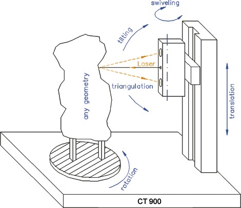
Le CT 900 capture les géométries de surface d'objets de n'importe quelle forme dans un trame de
points de mesure très dense. Ici, la tête de mesure se mouve verticalement, et l'objet fixé sur la
plaque tournante se tourne en même temps. Des mouvements additionnels de la tête de mesure
sont possibles pendant que l'objet tourne sur la plaque tournante ou reste dans une position fixe.
Le CT 900 a 5 degrés de liberté.
Le principe de mesure unique est caractérisé par des points suivants qui sont très importants pour
des applications techniques:
Mesure de surfaces extrêmement inclinées
avec un angle maximal de 88° entre la normale de la surface et le rayon
laser. Ainsi, les objets
plus compliqués peuvent être capturés en diminuant les opérations subséquentes en même temps.
Détection d'arêtes affilées sans dépassement des valeurs mesurées.
Cet effet a une importance considérable pour tous les algorithmes de traitement
ultérieur, p. ex.
la détermination rapide et exacte de courbes de géométries partielles pour la génération de
surfaces.
Une haute précision en combinaison avec la plus grande profondeur de mesure
possible.
Précision de </= 0,1 mm avec une profondeur de jusqu'à 900 mm. C'est le décuple ou, dans
quelques cas, le vingt-quintuple de procédures optiques traditionnelles.
Numérisation tridimensionnelle complète d'objets dans une seule opération, grâce
á des
cinématiques appropriées. Ces cinématiques sont constituées par la rotation de l'objet et/ou des
mouvements pivotants et basculants de la tête de mesure au même temps. Même si l'objet
consiste de surfaces très complexes et contre-dépouilles, peu de balayages suffissent pour obtenir
un nuage de points complet et dense.
Génération de nuages de points hautement précises. Le traitement ultérieur est
possible tout
de suite sans procédures coûteuses de longue haleine (p. ex. lissage, filtrage, réduction de bruit).
- Angle maximal de 88°
- Double triangulation - 2 caméras + 1 point laser
- Table tournante + 2 rails de translation
- Le CT 900 a 5 degrés de liberté
- Vision active
- Identification des arêtes lors du balayage
- Résolution plus élevée
-
NextEngine
Https://www.nextengine.com/indexSecure.htm
» See document: https://www.nextengine.com/indexSecure.htm
-
3000$
- Petits objets
- 45 minutes pour scan + reconstruction du modèle
- 3D + texture
- Lignes laser verticales
- Lumière blanche
- Mini polyworks pour reconstruire le modèle
de l'objet et mettre en registre les scans
- Fraunhofer Institute for Applied optics (IOF)
Http://www.iof.fraunhofer.de/index_e.html
Person to contact (kolibri)
Dr. Gunther Notni
Phone: +49 (0) 36 41 / 807 - 217
Fax: +49 (0) 36 41 / 807 - 602
email: gunther.notni@iof.fraunhofer.de
» See document: http://www.iof.fraunhofer.de/index_e.html
- Non-contacting 3-D shape measurement
- News
http://images.google.ca/imgres?imgurl=http://cleantechnica.com/files/2008/04/tireprint.jpg&imgrefurl=http://cleantechnica.com/2008/04/19/cool-tech-of-the-week-cordless-3d-sensor/&usg=__4Bosc2uv6MOsh-S3_4Ahmvzf7zQ=&h=275&w=357&sz=16&hl=en&start=32&tbnid=b7FpEPpsX7SieM:
&tbnh=93&tbnw=121&prev=/images%3Fq%3D3d%2Bsensor%26start%3D21%26ndsp%3D21%26hl%3Den%26client%3Dfirefox-a%26rls%3Dorg.mozilla:en-US:official%26sa%3DN
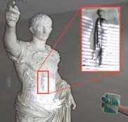
It looks like a childs toy from the 70s, but this new high-tech camera can record more than a
simple Polaroid. It can create a 3D image of almost anything, and you can take it almost anywhere.
Developed at the Fraunhofer Institute for Applied Optics and Precision Engineering IOF in Jena,
Germany, the Kolibri CORDLESS is the size of a shoe box and it weighs a little over 2 lbs. No
cables required, you just point and click. Several seconds later a detailed 3D image will appear on
a laptop. From there you can analyze and use the digital model.
* » Read more on products
Devices like this one are already available, but until now they were too big and heavy to carry
around. The next best model is twice the size and weight of the Kolibri CORDLESS. Why is the
Kolibri so much lighter and smaller, you ask? LED lights, of course. 3D cameras(theyre actually
called sensors) shine a projector light on an object, and two cameras record the image from two
different angles. Then a computer compiles the data into a 3D image. By using LEDs, the Kolibri
3D sensor replaces larger, hotter, and more power-hungry Halogen bulbs. However, LEDs are not
without flaw:
This poses an additional challenge, as the LEDs shine in all directions. To ensure that the image
is nevertheless bright enough, the light has to be collected with special micro-optics in such a way
that it impacts on the lens.
3D Tire tracksThe Kolibri CORDLESS could provide valuable services to doctors, forensics experts,
industrial workers and more. Crime investigators could take 3D images of important evidence
without disturbing the scene. Doctors could use exact, custom images of patients for sleep masks,
surgery prep, or even prosthetics. Engineers or designers would have better models of tight, hard-to-reach
spaces in buildings, structures, or products. Archaeologists could exactly record carvings or
etchings in stone, wood or clay - some of which might be too delicate for moldings. Artists, no
doubt, could have a field day. It might not be the greenest new gadget on the block (LEDs dont
automatically mean green), but users will no doubt increase their productivity as they perform
work, and who knows what kind of important research could benefit?
The Kolibri could replace plaster as a reliable source for 3D models, and easily expand into spaces
and places where plaster cant go. Though not yet available for sale, Fraunhofer IOF will showcase
their new gadget at the Control trade fair in Stuttgart, Germany, April 21-25 (Hall 1, Stand 1520).
Via Eureka Alert
Tweet This Post
Tags: 3D, camera, digital, gadget, tech, technology
- Kolibri FLEX Mini
- 2 lasers à 90 degres
- Rotation de l'objet (petits volumes)
- Kolibri
Self-Calibrating 3-D Measuring System
Vergrößerung!
Prototype of the 3-D system of measurement system "kolibri"
Vergrößerung!
3- D image of an air suction fitting
Vergrößerung!
3-D image of a head of a statue
The self-calibrating optical 3-D systems of measurement,
known as "Kolibri", functions
according to the following patented principle:
The object to be measured is illuminated from at least two directions by two 90° rotated sequences
of fringe patterns. Thanks to a new approach based upon a photogrammetric principle, it is possible
to simultaneously calculate the 3-D coordinates and all orientation parameters on-line using only
the obtained phase values. In this way, the device is insensitive to time-dependent instabilities in
the measuring system, caused by temperature changes, vibrations, etc. Thus, unrestricted by
special measuring rooms, the high-precision measuring equipment can even be used under
production conditions.
The self-calibrating measuring systems allow the user to freely choose the camera position as well
as the use of different observing optics. Therefore, the measurement area can be freely determined,
for example to measure selected details with a higher resolution. Even objects with a complex form
can be completely registered as a result of the option to use several cameras simultaneously. Due
to the special self-calibrating strategies, the partial views obtained are registered in a world
coordinate system. Thus, the views are automatically composed to a 3-D panorama image without
additional marker points or time-consuming matching procedures. The system is not restricted to
one measuring field. According to customers' requirements, it can be adjusted.
360-deg 3D Measurement systems
System line "kolibri"
"kolibri flex" - mobile selfcalibrating optical 3-D measurement system
"kolibri ROBOT"
"kolibri CORDLESS"
"kolibri-portal" measurement portal,
measurement of large objects
"kolibri II" - multi-view 3D measurement system
"G-Scan" - Mobile 3D measurement system, 3D face measurement
Person to contact
Dr. Gunther Notni
Phone: +49 (0) 36 41 / 807 - 217
Fax: +49 (0) 36 41 / 807 - 602
email: gunther.notni@iof.fraunhofer.de
- Two 90° rotated sequences of fringe patterns
- 3-D coordinates and all orientation parameters
on-line using only the obtained phase values.
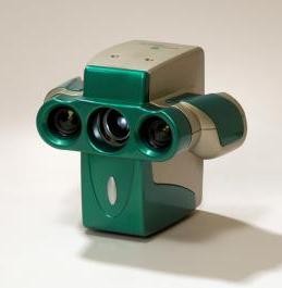
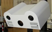
- Kolibri CORDLESS
kolibri CORDLESS
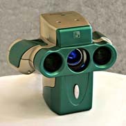  
Handheld cordless optical 3D measurement system
Sensorhead
Stereo camera setup with LED based fringe projection
Produktblatt download
Measurement principle
Fringe projection with two grating structures rotated by 90° to each other
Whole body measurement by the use of free moving sensor head
Highspeed image projection and acquisition
Features
Virtually unlimited freedom in sensor placement
Hand-held measurement through 60 Hz fringe projection
No restrictions in sensor positioning by means of cordless data transmission
and battery power
supply
Self calibration of measurement system
Alternatively software based matching respectively self calibration for whole
body measurement
Optionally capture of color and texture in high resolution
Applications and offer
3D data for quality control, rapid prototyping, design, CAD/CAM, archaeology
and criminology
Development and manufacturing of equipment according to the specific client
need's
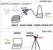
System Parameters Scheme of 3D measurement set-up (self calibration by means
of optional
linking camera)
Scheme of 3D measurement set-up (self calibration by means of optional linking camera)
Single measurement fields:
220 mm x 170 mm
550 mm x 425 mm
Measurement uncertainty:50 µm ... 150 µm
Sequence duration: < 0,25 s
Number of views: free
- Wireless 3D camera
- LED based fringe projection
- 60Hz projection
- Kolibri ROBOT
kolibri ROBOT
Handheld cordless optical 3D measurement system
3D sensorhead3D sensor head
SensorheadMeasuring of a seat with kolibri ROBOT
Measuring result of the seatMeasuring result of the seat
Sheet metal and Measuring result;comparision with CAD model.Sheet metal and Measuring
result;comparision with CAD model.
pds as download download
Measurement principle
Stereo based fringe projection with 2 patterns rotated by 90° to each other
Automatic whole body measurement using changeable sensorhead position
Sensor head handled by robot
Features
Free sensor head positioning
Total planning freedom through 6 motion axes
Self calibration of measurement system
Multi-view measurement without markers or other devices
Mobile robot support
Our offer
3D data for quality control and rapid prototyping
Use in tool manufacturing, mould making, CAD/CAM, design, etc.
Development and delivery of equipment according to the specific client needs
System Parameters
Single measurment fields: 460 mm x 350 mm
Measurement duration: 3 - 5 s
Number of views: free
t uncertainty:25 µm
Sequence d
Contact
Dr. Gunter Notni
Tel.: +49 (0) 36 41 / 807 - 217
Fax: +49 (0) 36 41 / 807 - 602
email: gunther.notni@iof.fraunhofer.de
- Handheld cordless optical 3D measurement system
Biris
- Défocalisation lentille + masque (1 caméra = N caméras)
- Laser Requis
- Ligne
- Point
- Sous utilisation du capteur CCD
- Vitana
» See also: ShapeGrabber
http://www.shapegrabber.com/
- ShapeGrabber
http://www.shapegrabber.com/
Contact Us
ShapeGrabber Headquarters
1900 City Park Drive
Suite 304
Ottawa, ON K1J 1A3
Canada
Telephone: 1-(613) 247-1707
Fax: 1-(613) 247-1406
========
At ShapeGrabber, measuring complex shapes is our specialty. We design, manufacture and sell
industrial 3D inspection systems ideal for measuring complex shapes such as injection molded
plastics and castings that are otherwise too time consuming, costly, or difficult to measure.
ShapeGrabbers state-of-the-art inspection solutions are the next generation in optical non-contact
measurement systems. Considered to be one of the industrial pioneers in the field, ShapeGrabber
has been supplying 3D scanning solutions for more than a decade.
Our 3D scanning systems are used by customers in the automotive, aerospace, medical, and
other industries. They are used for quality inspection, dimensional troubleshooting, design and
modeling.
ShapeGrabber systems operate using a fraction of the time and resources compared to CMM
systems while providing NIST-traceable full surface data of even the most complex plastic injection
molded parts, stampings, castings and more. Our solutions help manufacturers to dramatically
reduce their inspection costs, improve their product quality, rapidly conduct first-article inspection,
quickly troubleshoot fit problems, and provide documented proof that they are meeting
specifications.
ShapeGrabber systems are turnkey solutions that include all required hardware, software, CAD
workstation, installation, training, and a full year of support. ShapeGrabber continues to pioneer
innovation in 3D measurement, focusing on ever-greater accuracy, system flexibility, ease of use,
and speed.
» See document: http://www.shapegrabber.com/
- Tables avec moteurs
- Systèmes portables (rail + trépied)
- 3 Différentes têtes de balayage (différente
résolution)
- Http://www.exocortex.org/ben/articles/nrc_sushi.html
» See document: http://www.exocortex.org/ben/articles/nrc_sushi.html
- CNRC
Ottawa
http://www.nrc-cnrc.gc.ca/
» See document: http://www.nrc-cnrc.gc.ca/
» See also: Vitana
- Donne la distance pour 1 ligne ou un point
- Trid - LVSN ULaval - F.Loranger,
D.Laurendeau et al 1997-1999
» See also: TRID
LVSN, Québec
|