TP5

Adding Virtual Objects

by Saeed Sojasi


Goal of Assignment

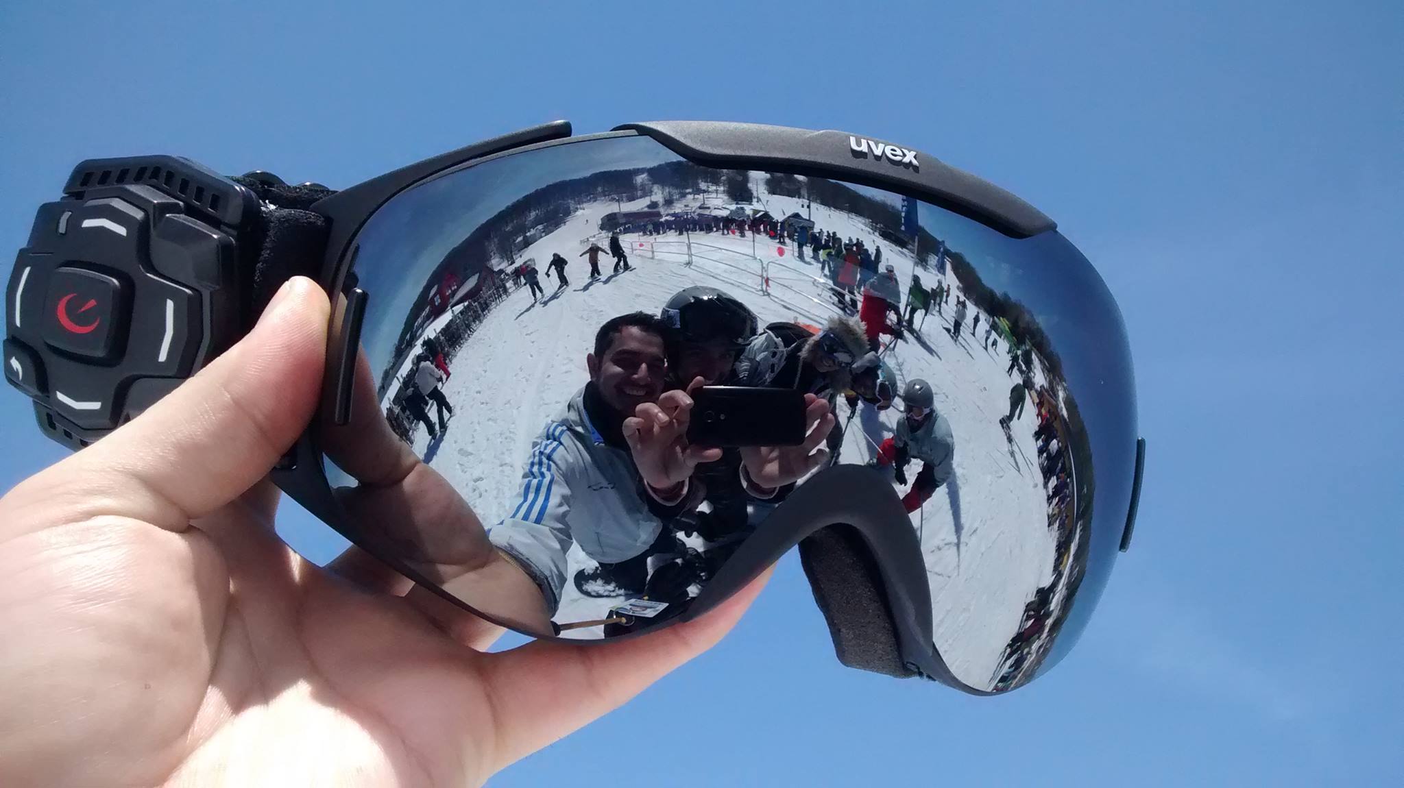
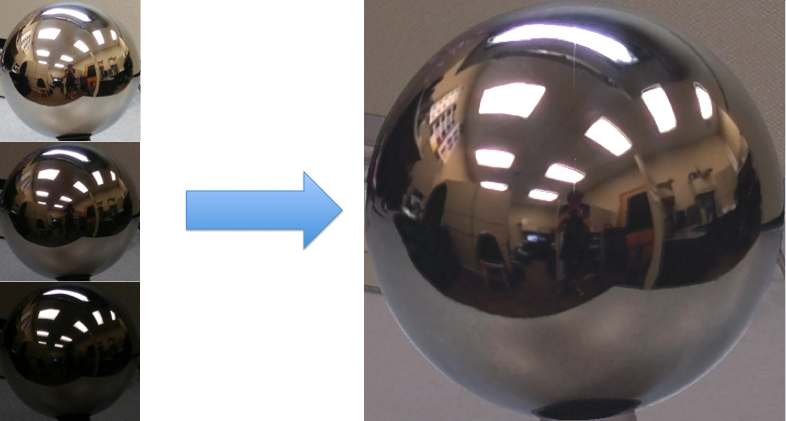
The goal of this project is to familiarize with high dynamic range (HDR) imaging, image-based lighting (IBL), and their applications. We should create HDR images from sequences of low dynamic range (LDR) images and also composite 3D models seamlessly into photographs using image-based lighting techniques. High-dynamic-range imaging (HDR) is a set of techniques used in imaging and photography to reproduce a greater dynamic range of luminosity than standard digital imaging or photographic techniques can do. It is a digital photography technique whereby multiple exposures of the same scene are layered and merged using image editing software to create a more realistic image, or a dramatic effect. The combined exposures can display a wider range of tonal values than what the digital camera is capable of recording in a single image. Most methods for creating HDR images involve the process of merging multiple LDR images at varying exposures, which is what we will do in this project. HDR images have a lot of applications such as contrast enhancement, hyper-realistic art, post-process intensity adjustments, and image-based lighting. For this project we will focus on their use in image-based lighting, specifically relighting virtual objects. We need a 360 degree image. Capturing 360 degree image is difficult with standard cameras, for solving this problem we capture an HDR photograph of a spherical mirror, which provides the same omni-directional lighting information. In this homework, we will take the spherical mirror approach. With this panoramic HDR image, we can then relight 3D models and composite them seamlessly into photographs. In conclusion, this project has 4 main part: 1- Data collection 2- Produce HDR image 3- Panoramic transformation 4- Blender .

Recovering HDR Radiance Maps

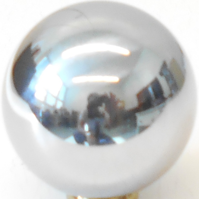
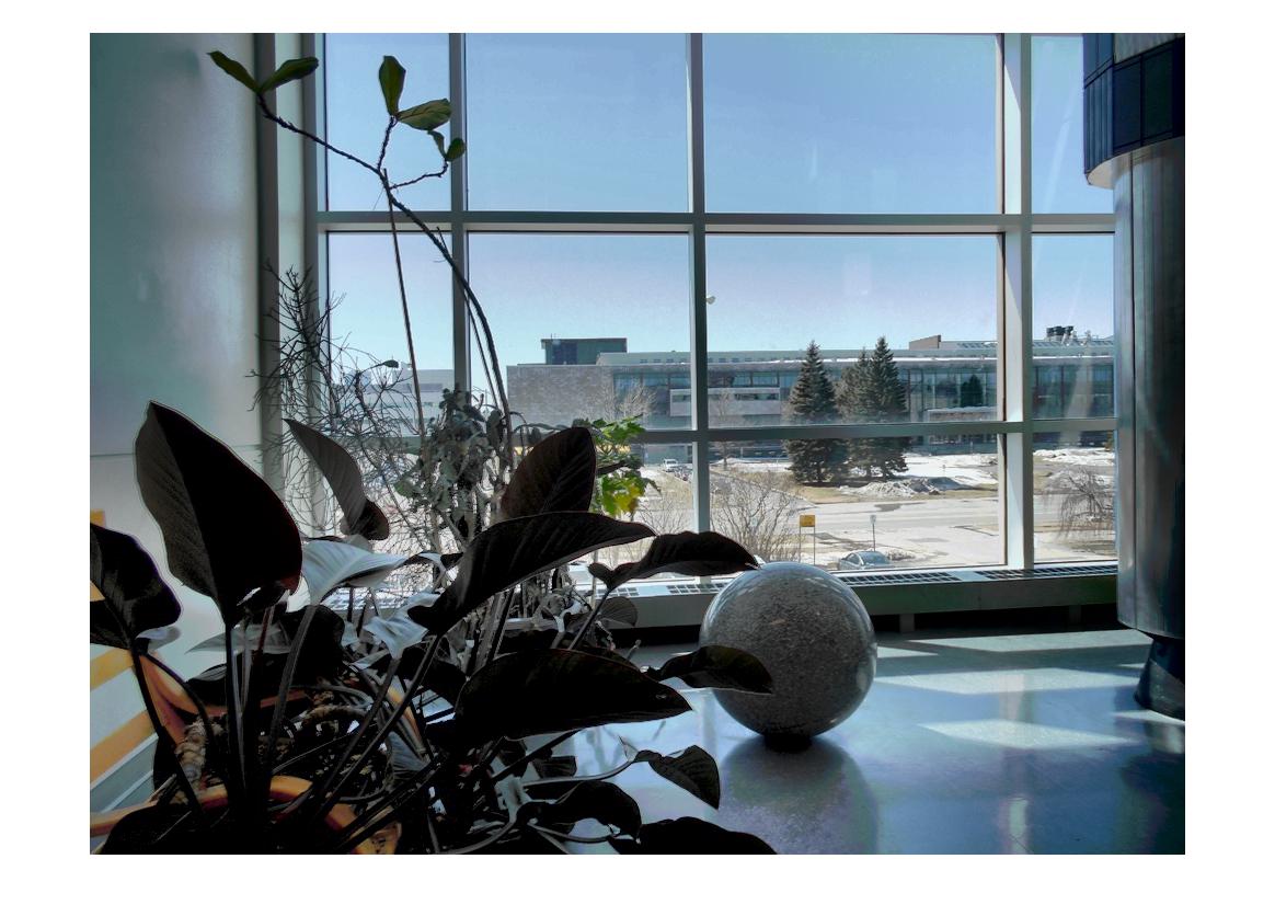
In this part we need to capture multiple exposures of a metal ball placed in the scene of interest, and merge these exposures into one image with high dynamic range. For this purpose we will need equipment:
o Spherical mirror
o Camera with exposure control
o Tripod / rigid surface to hold camera / very stead hand
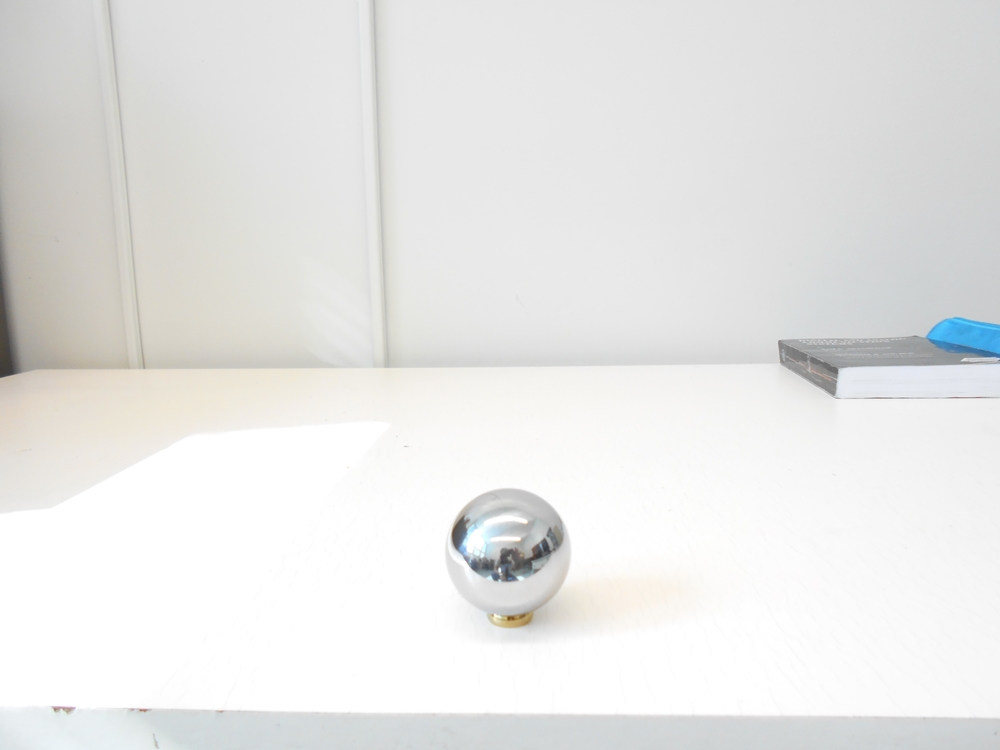
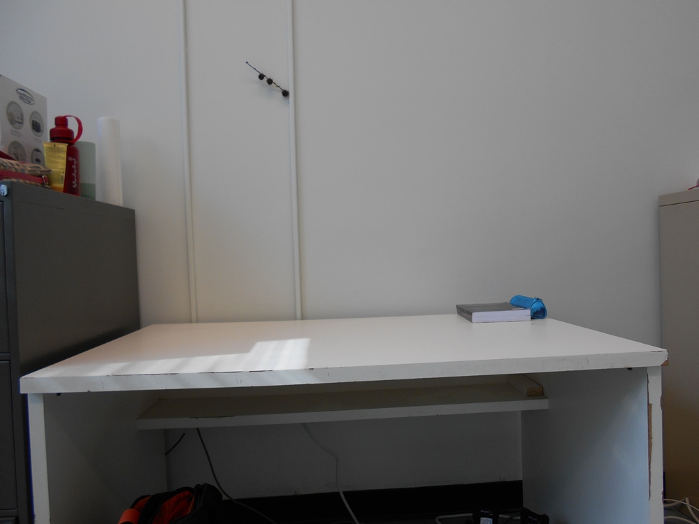
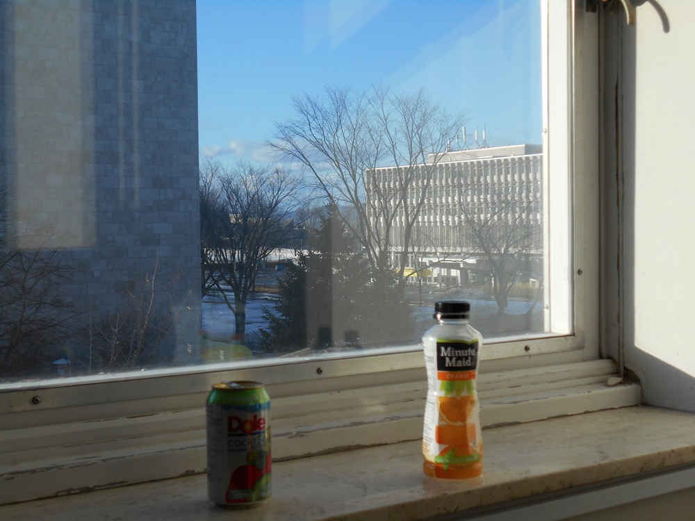
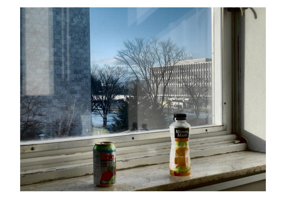
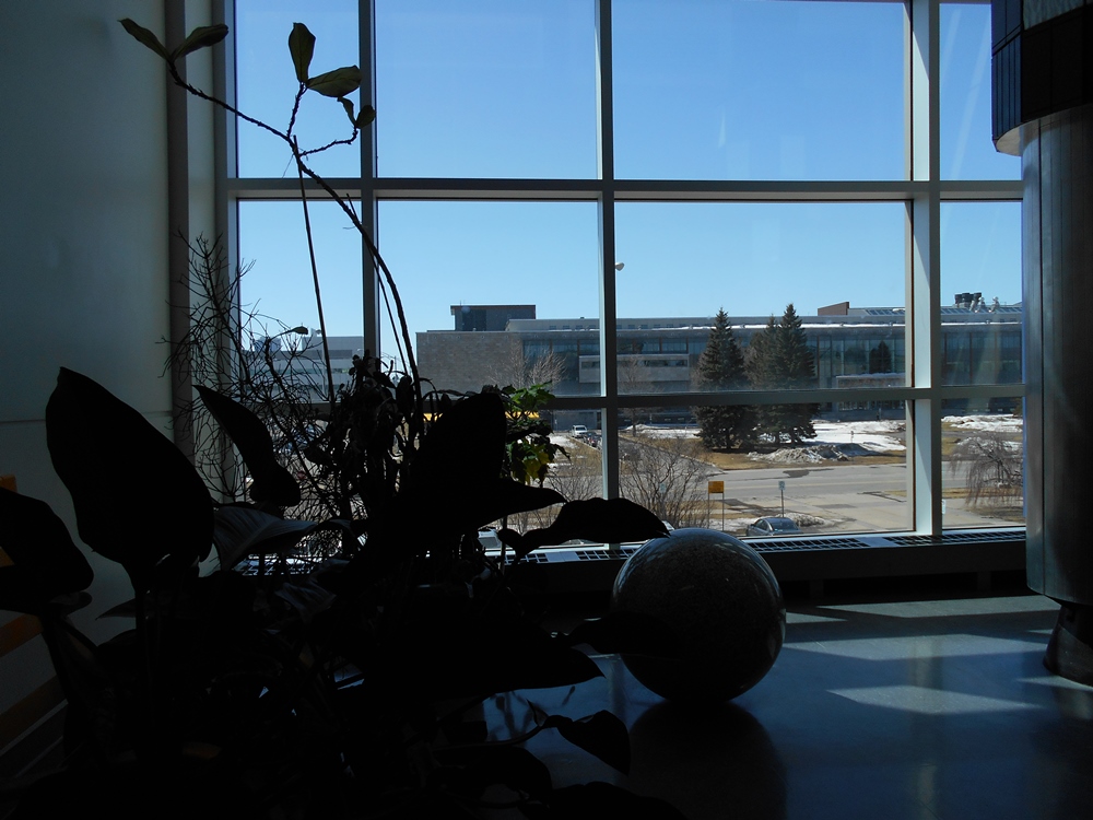
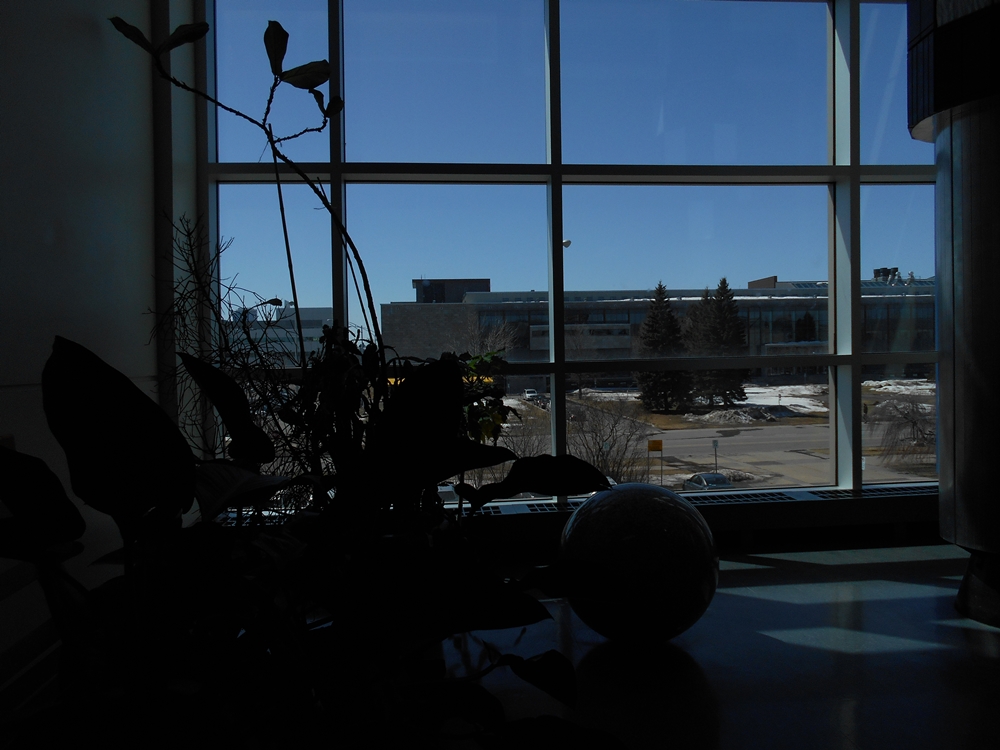
For doing this part we should find a good scene, we want to put our objects on the scene. We use a tripod for camera and spherical mirror and then take photo with different exposure (at least three different exposures). Finally, we remove mirror from the scene and take photo with normal exposure. This is background image.


LDR merging


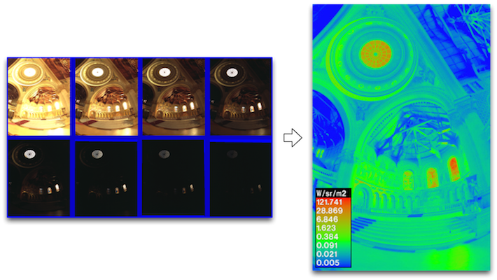
We want to build an HDR radiance map from several LDR exposures. For this purpose I used the idea of [Debevec and Malik 1997] (see the code ‘radiance_map.m’). Radiance is light or heat as emitted or reflected by something. Irradiance is the flux of radiant energy per unit area (normal to the direction of flow of radiant energy through a medium). In photography, exposure is the amount of light per unit area (the image plane illuminance times the exposure time) reaching a photographic film or electronic image sensor, as determined by shutter speed, lens aperture and scene luminance. The observed pixel value Zij for pixel i in image j is a function of unknown scene radiance and known exposure duration:

Zij = f(Ei x Δtj )

Where Ei is unknown scene radiance at pixel i and Δtj is known exposure time. We cannot solve this equation by f, but f is monotonic. So, we have:
f -1(Zij) = Ei Δtj

We put g=ln(f -1). Then we have:
g(Zij) = ln(Ei) + ln(Δtj)

Solving g is impossible because we know neither g nor Ei. We know the scene is static and while we do not know the absolute value of Ei but we know the value remains constant. For having good results we assume two additional things:We expect g to be smooth and Each exposure only gives us trustworthy information about certain pixels. In conclusion, it mainly consists of two steps: in the first step we identify the response curve ‘g’. This curve maps pixel values to the log of exposure values (see the code ‘g_curve.m’). In the second step we maps observed pixel value and exposure time to radiance (see the code ‘HDR.m’). Before these two steps, points are selected automatically (see the code ‘select_pixels.m’). The number of select pixel must N(P-1) > 256 (suggested in the paper). Finally, I used tonemap function in MATLAB for render high dynamic range image for viewing.

Results

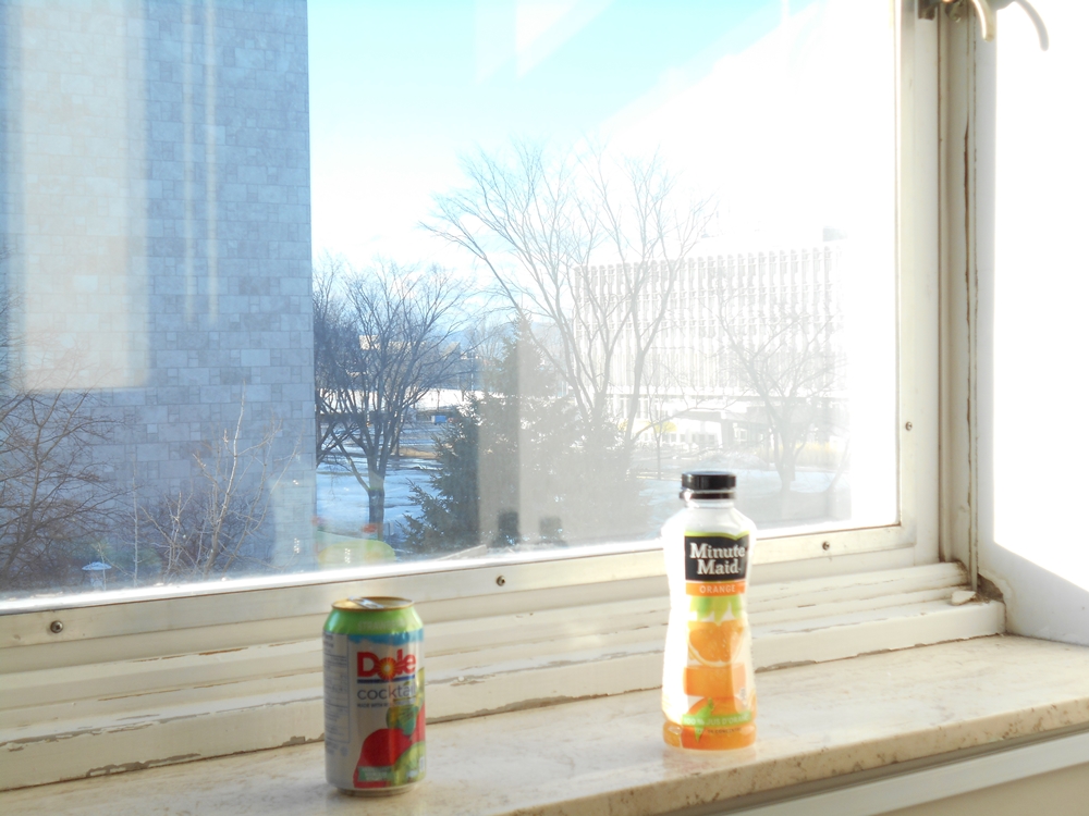
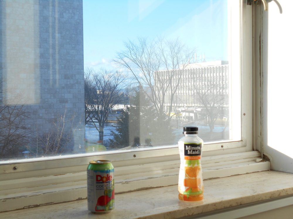
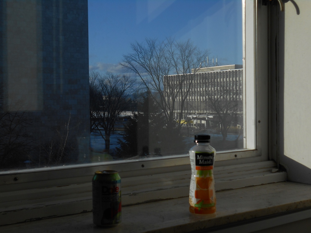
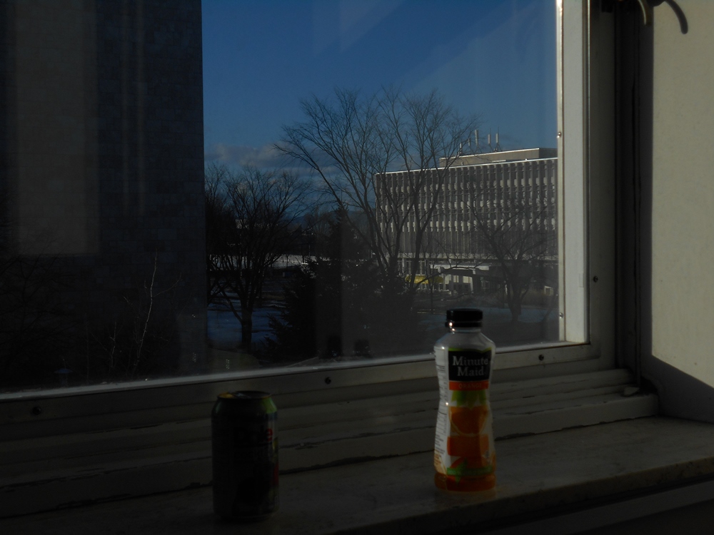
I took five images with different exposure time. I started from +2 to -2 in camera mod. [+2 +1 0 -1 -2].
The results of this part are shown below:
The center image is normal image with 0 exposure:


We can see the results of these images as below:
The automatically selected pixels is shown below:


The reconstructed radiance map is shown on the left and the response curve (g-curve) is shown on the right:


Finally, we can see the tone mapping as below:


Discussion

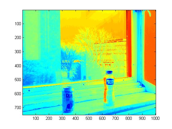
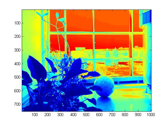
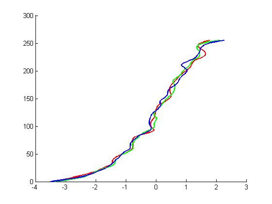
The result of this part is very good. I used a tripod to took images. As you see, the response curve (g-gurve) is very smooth. So, we have a good tone mapping result. We cannot take image as this result by camera. I want to show that, tripod is so important in take sequence images. If we do not use a tripod, we wont have smooth response curve then our result wont be good. I repeated this part with another scene and I intentionally a little moved my hand in first image. We can see the results of this part:

At the center image is normal image with 0 exposure:


The reconstructed radiance map is shown on the left and the response curve is shown on the right:


Finally, we can see the tone mapping as below:


Discussion

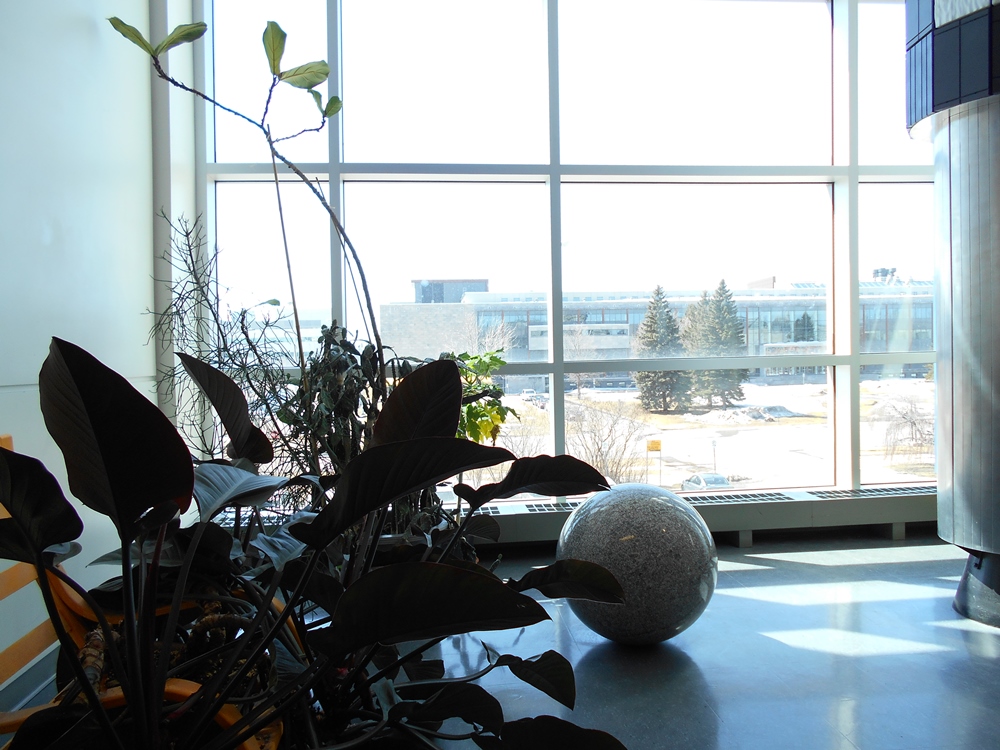
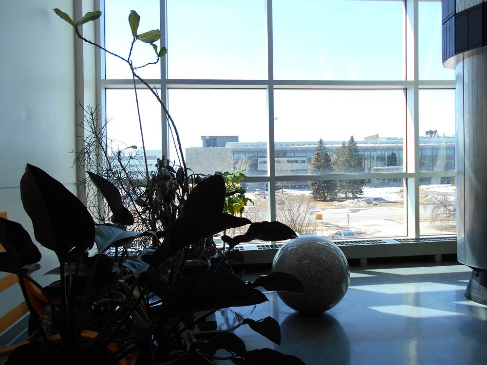
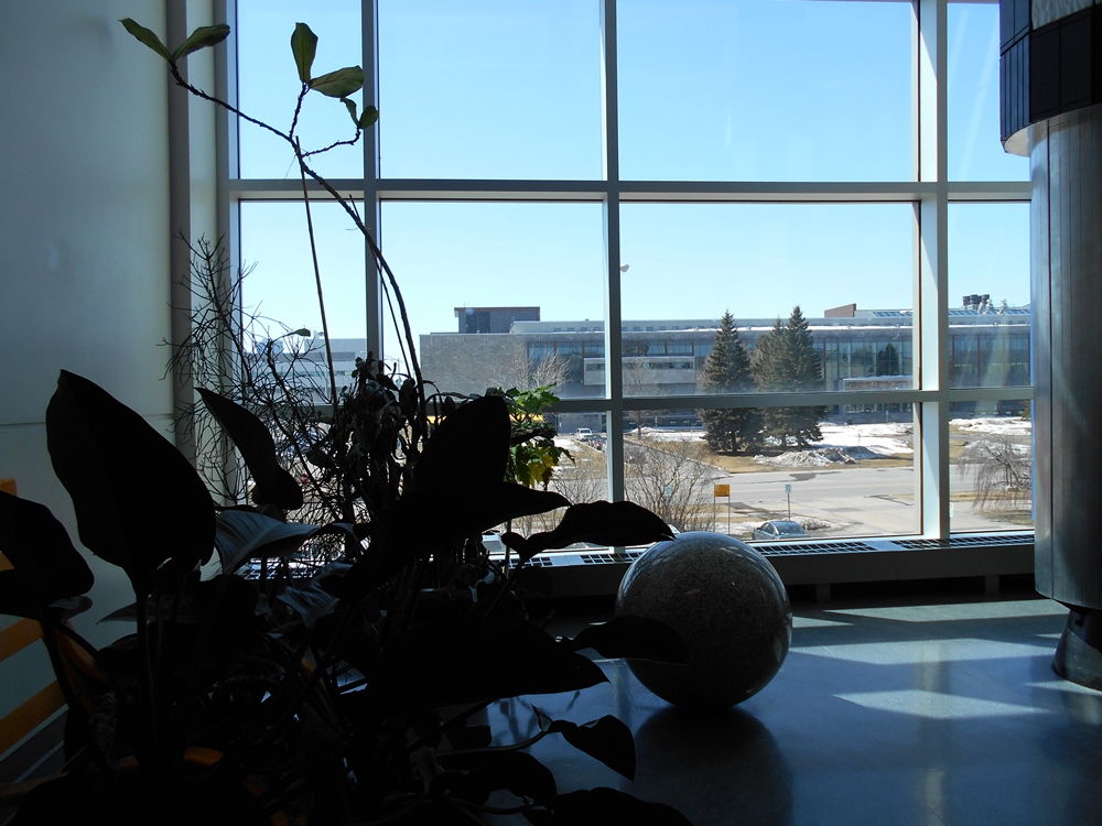
As you see, the response curve is not very smooth. So, our tone mapping image is not very good. We have artifact edges in leafs.

Panoramic Transformations

Panoramic transformation is transforming HDR image to the equirectangular domain in order to be used for image based lighting. To make this possible, I used two ways. First,To do this part, the DHR images used was the HDR images generate using the method called response function. The general process to estimate the panoramic transformation of the HDR images were the following: first, estimate the Normal vector of each pixel. To do this, first the (u,v) coordinate of each pixel was estimate transforming each pixel in a range between [-1 1]. After known the (u,v), the Normal Vector coordinates were the following N = [u v sqrt(1-u^2-v^2)]. The value of N only was estimate for the pixel that had a radius < = 1. Then, Reflection vector was estimate for each pixel using the following equation: R = V - 2 .* dot(V,N) .* N, where R is the reflection vector, V is the viewing direction in my case V = [0 0 1], and N is the normal vector that was estimate before. Using the value of the Reflection vector, it is possible estimate the value of phi and theta. In my case the values of theta were calculate using the following equation theta = atan2(Ry/Rz) and phi was calculate using the following equation phi =acos(Rx). Now, to estimate the values of latlon the Matlab function called TriScatteredInterp was used, but to use this function the function phi, theta and the HDR image were reshape in a column vector. Also, to estimate the values of latlon was used the Matlab function meshgrip. The meshgrid function was used as follow:[thetas, phis] = meshgrid([pi:pi/360:2*pi 0:pi/360:pi], -pi/2:pi/360:pi/2). I could not get good results with this way. Then, I tried to do inverse of this process. First, I obtaind ϕ and θ by meshgrid. Where ϕ∈[-π,π],θ∈[-π/2,π/2]. Then I go from Sphere coordinate to Cartesian coordinate by function sph2cart. The result of this part is reflection vector R. V is the viewing direction and in my case it is V = [0 0 1]. In the next step, I calculate normal vectors by following equation: R = V - 2 .* dot(V,N) .* N, where R is the reflection vector, V is the viewing direction in my case V = [0 0 1], and N is the normal vector. N = (x, y, z) where (x,y) are point on sphere. Finally, I used Interpolate (function interp2) to estimate color of each pixel. My approach was to compute (ϕ,θ)→Ix,y. (see the code 'sphare2rect.m ')

Results

The results of this part are shown below:
First, I took three images in different exposure time:


I manually cropped them and results are shown below:


Then I used these three images to produce HDR image. I used the technique that I mentioned in Recovering HDR Radiance Maps part except tone mapping section. I saved recovered radiance map in hdr format. The result of HDR is shown below:


It is a HDR image that I saved in HDR format. In this part I did not use tone mapping result. Because tone mapping images is not good for next part. We can see the result of tone mapping on the sphere as below, but I never used it in the equirectangular HDR image.


Finally, I used Panoramic Transformations technique on HDR image and equirectangular HDR image is shown below:


Discussion

I saved HDR images in png format to display in website. The results in above are png format but I used HDR format to got the results and do next part.

Rendering Synthetic Objects into Photographs

In this part, we use our equirectangular HDR image as an image-based light, and insert 3D objects into the scene. This part consists of 3 main parts: modelling the scene, rendering, and compositing. For doing this purpose we use a render software.


I used blender software to do this part. First of all, I selected my 3d object and put them in the scene that I selected previously(in above). I defined the position and texture of objects. Then I rendered by software. I used equirectangular HDR image that I got in previous section to blend objects. This is a rendered image (R). Then, I deleted object and again rendered empty scene. This is rendered without objects (E). Then I created a mask for objects. I did this procedure same as the website. Now I have mask of objects (M). Left one is rendered image with objects, center one is rendered image without objects, and right one is mask of objects.


Finally, we will use the above rendered images to perform "differential rendered" compositing. I put the name of rendered image with objects R, rendered image without objects E, Mask M, and background image I. The final composite is computed with:
composite = M.*R + (1-M).*I + (1-M).*(R-E).*c
Whre c modulate the light effects of the insert object. I put amount of c initially. First I set c = 1 and then c = 2.
(see the code 'composite.m')

Result

The results of this part are shown below:


Discussion

As we see in the result, some objects have good reflection and we can see the effect of equirectangular HDR image on them. Transparent objects like sphere have good results, but in dark objects we can not see clear effect of equirectangular HDR image. We see a little effect on Dragon and almost nothing effect on Suzanne. We can see the window and light reflection on teapot, but it is not clear than sphere.The best result is sphere, because it is a mirror.

Now, I again use my equirectangular HDR image (same as above)that I got it in the above for rendere the homework example.

Result

The results of this part are shown below:
The left one is HDR image and the right one is equirectangular HDR image:


The scene of homework example is shown below:


The final result with my equirectangular HDR image is shown below:


Discussion

The results are same as above except, First our viewpoint are changed and I put Y = -Y in the equirectangular HDR image ( it is like flip image), so we the window in the right part of sphere, whereas the window effect was on right part of sphere in the previous part.

Make new scene with new Objects

In this part, I took images with different exposure time (same as previous exposure time) in another room. I took this images in the evening. Also, I used another scene and 3D objects. I downloaded 3D objects from www.tf3dm.com. The image of new scene is shown below:


The images with different exposure time are shown below:


I manually cropped them and results are shown below:


I used the Recovering HDR Radiance Maps technique on these three images and saved it as a HDR image and after that I used the Panoramic Transformations technique and produced the equirectangular HDR image. The results are shown below:


After that, I modelled local scene and inserted objects.


After that, I used blender software to produce rendered image with objects (R) (the left one), rendered image without objects (E) (the middle one), and object mask(M) (the right one):


Finally, I used composite function to produced final result.


Discussion

The same as previous result, transparent objects have good reflected. We can see the effect of equirectangular HDR image on the transparent objects. The result of sphere mirror is good. We can see a little effect on bottle. Also, the second sphere on transparent part has good result. other opaque objects like goose, lemon, shoe, glass,and toy do not have good results. Basketball ball in black part has small effect. Region between basketball and drawer is not good at all. Because, both colour are orange and they made a artificial shape at overlap region. So, basketball ball is not same as real ball in this result. I want to mention that, our mirror sphere is smaller than example mirror sphere and surface of our mirror sphere is not very clear and transparent, so my HDR result is not as good as example.


Reference

Debevec and Malik 1997
www.tf3dm.com