Computatioanl Photography, Winter 2015
Mahdieh Abbasi
Email: mahdieh.abbasi.1@ulaval.ca
Abstract
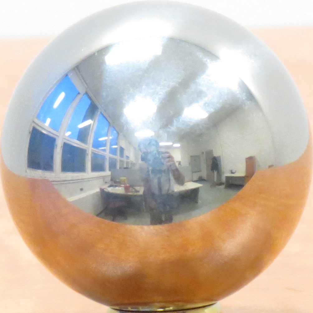
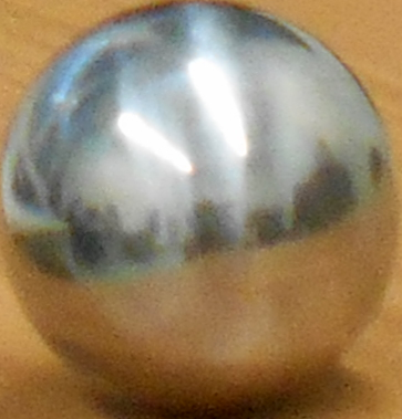
To add some virtual objects to a scene, we should relight the objects. In the real world, objects reflect all lights from the environment with respect of their material. Therefore, for virtually relighting the objects, we should have all lights from all angels. For taking all light information from environment, we need to take a 360 degrees panoramic HDR(High Dynamic Range) picture. One way to produce such HDR picture is to take multiple HDR images and stich them so that making a panorama HDR picture, which has all light information. Another way is using a mirror sphere(such sphere reflects all lights of the environment), then take a HDR picture from this sphere. In this assignment, we firstly take some LDR pictures from the sphere mirror so that produce a HDR picture. Then, we transform all lights in the sphere into an equirectangular. Finally, we this equirectangular as input to Blender software in order to relight the added objects.
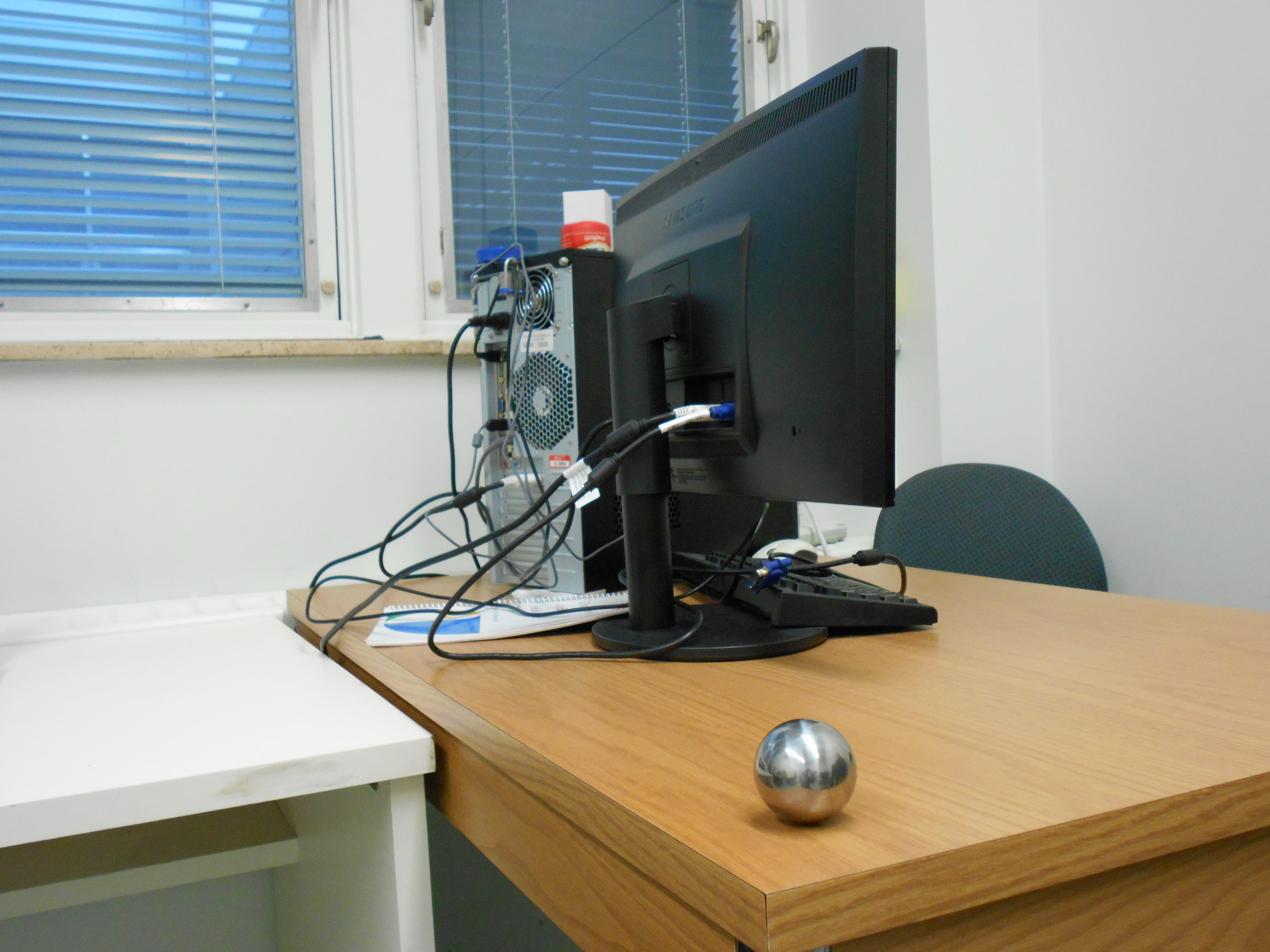
Image collection
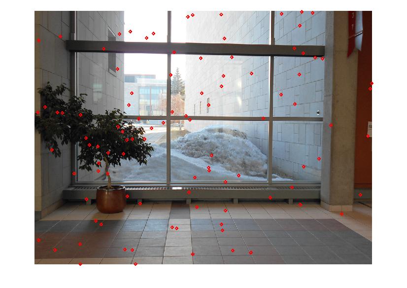
To collect data, I used a tripod, a mirror sphere and a simple digital camera, which takes pictures in different exposures. I placed the mirror sphere, fixed the camera in a location by the tripod, and took 5 photos from the scene in different exposures. One image is taken from the same scene without the sphere. All spheres in different exposures are extracted from the taken images. I need them for making a HDR image. It worth to mention that the camera should not be move, while we take pictures, since even slightly moves, we faced with alignment errors. IN other words, the radiance map algorithm assumes that one pixel coordinate corresponds to the same world coordinate in all LDR images. This is only true, if the camera does not even slightly move between the shots. In addition, the scene , which we take photos from it, does not change at all.
Construct HDR from LDR images
Before I explain the methodology of constructing a HDR image from this paper, let me to explain HDR image concept. HDR image contains a large range of luminance levels, while LDR image has a predefined and limited domain of luminance, e.g. [0,255]. Our camera can just show this limited domain, not a high range domain. Our goal is presenting the large range luminance at one picture(called HDR image).

To resolve this problem, we can take several LDR images in different exposures in order to create a radiance map. In other words, a radiance map is an image with scene radiance as values for the pixels. In the literature, radiance is the amount of light emitted from a certain area. So, scene radiance is the amount of light emitted from a visible object in the scene. Let consider Z_ij value of a pixel i in the LDR image j, which is taken in the exposure time t_j, and E_i is scene radiance value for the pixel (i). All we know is the value of Z_ij and t_j, and also know that the value of Z_ij is proportional to multiplying of E_i and t_j:

The function f is monotonic and invertible, by taking the natural lograithm, and defining we reach the equation:
Our goal is finding the curve g and scene radiance value for pixel i,E_i, which are computed by solving linear equations. The linear equation consists of two terms, one loss function, and smooth term. The loss function says the g(z_ij) - ln(E_i)- ln(t_j) should be minimum, and the smooth term says the g curve should be smooth. The effect of smoothness is controled by parameter λ To solving the system of linear equations, we should have enough pixel values. As the paper says the number of pixel values (N) should satisfy the equation: N(p-1)> 255. For example, HDR image can be recovered from 3 LDR photographs (p) by at least 130 pixels. Let me mention that we sampled the pixels from the input images (I_j) where the distribution of values of the sampled pixels is uniform. In other words, we should select pixels where their intensity value evenly distributed in the range of [Z_min, Z_max], e.g. [0,255]. Finally, when we have the g curve, we can compute the radiance value for all pixels(i) of the HDR image by wieghted averaging of pixel values of LDR images (j) in different exposures. 
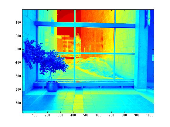
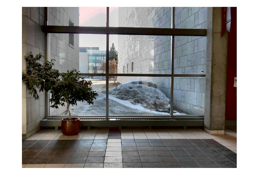
I took a series of photos in different exposures (5 photos), then selected 100 pixels which the distribution of their intensity is uniform. I did this by dividing the interval [0,255] to 20 sub intervals, which the number of pixels in each sub interval is 5. Then, I took values of the pixels from each channel (red, green, blue). For example, for channel red, I get pixel values, z_ij where i = 1,..., 100, and j =1,...,5. From Z_ij and t_j, the function g is estimated for each channel. By using the g curves, I computed radiance scene, E_i. Finally, a HDR image obtained from tonemap function of Matlab.
 |
 |
 |
 |
 |
| 100 selected pixels values | g curve for red, green, blue channels |
|  |
| radiance map | Final image by tonemap |
|  |
In another scence, I and my friend put a mirror ball, took 3 photos in different exposure (-2, 0, 2), then cropped the photos to extract the spheres. It worth to mention theat the HDR image is dependent on the parameter λ. If λ set to small number like 1, the g curves for the red, green, blue channel are not smooth. Therefore, we have to set the parameter by experiments. For example, I show two HDR images that their λ are different. Therefore, these expreiments say that the small value for λ, the more curviture the g curves, and finally the quality of HDR image is reduced.
| λ | g curve | HDR image |
| 5 |  |
 |
| 50 |  |
 |
| λ in resultant HDR | LDR: exposure 2 | LDR: exposure 0 | LDR: exposure -2 | HDR image |
| 13 |

|
|
|
 |
| 50 |
|

|
|
|
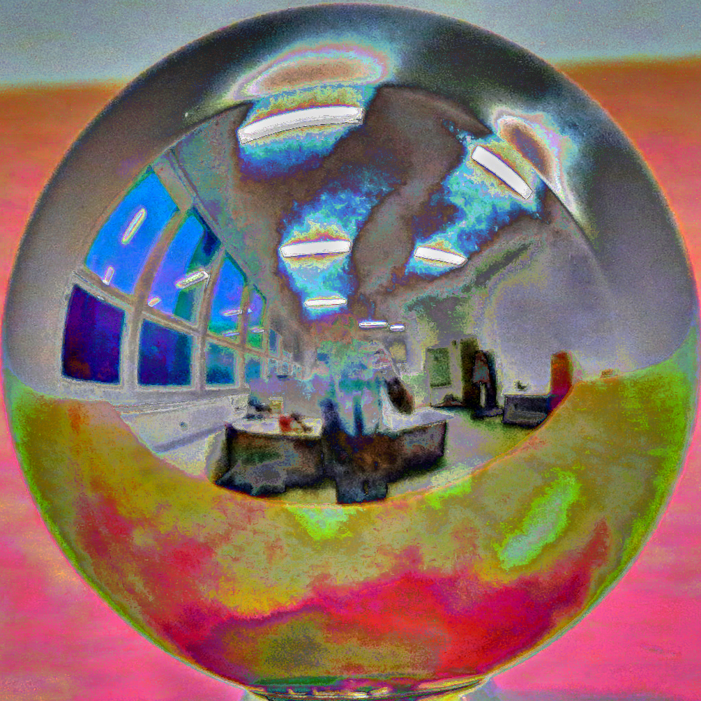
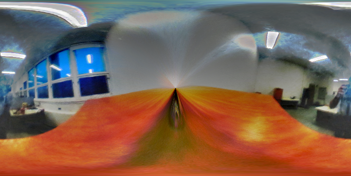
Panoramic transformation
In the previous section, we state the methodology of obtaining a HDR image from a series of LDR images. Now, come back to the main story, which we want to relight some added objects. For doing this, we want to capture all light information from all directions. A mirror sphere can capture all lights from a scene. We take several images in different exposures, and produce a HDR image in order to get all scene radiance. Then, we can give the HDR image to Blender to relight the added objects. Since Blender takes an equirectangular image as input not a sphere, we have to transform from sphere to equirectangular. I followed the sequence to make this transformation:
|
 |
|
 |
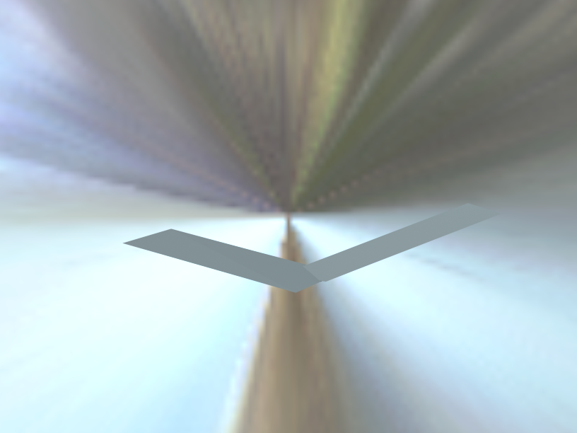
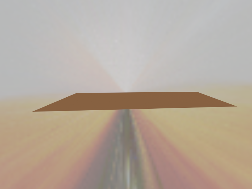
Relight the virtual objects by Blender
I followed exactly the steps that indicated in this assignment. In a nutshell, firstly I inserted my background in Blender by pressing N, and check Background Image radio box, then open and add my background image. Next step is creating a plane where the mirror sphere and the virtual objects will be there. I made a plane by shif+A and add plane and in its edit mode, I moved it till it aligned with my surface. The color of the plane is the color of place where the mirror sphere was. After that I inserted and align my objects on this plane, define material for the objects. For creating a new materiale for an object, I add texture picture in material panel of the object and with respect to the material, I set shader of it( I exactly follow this tutorial for creating new material) Finally, add my rectiangular HDR image, which is obtain as I said above, to World tab in Blender, and render the scene. Once the blended scene is created, I removed the inserted objects and render a empty scene. As the last step, I created a mask for my objects by Blender(for reading more about how to create mask, you are recommended refer to TP5).
| Rendere objects scene | Empty scene | Mask |
 |
 |
 |
 |
 |
 |
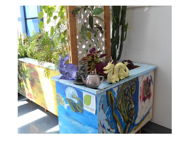
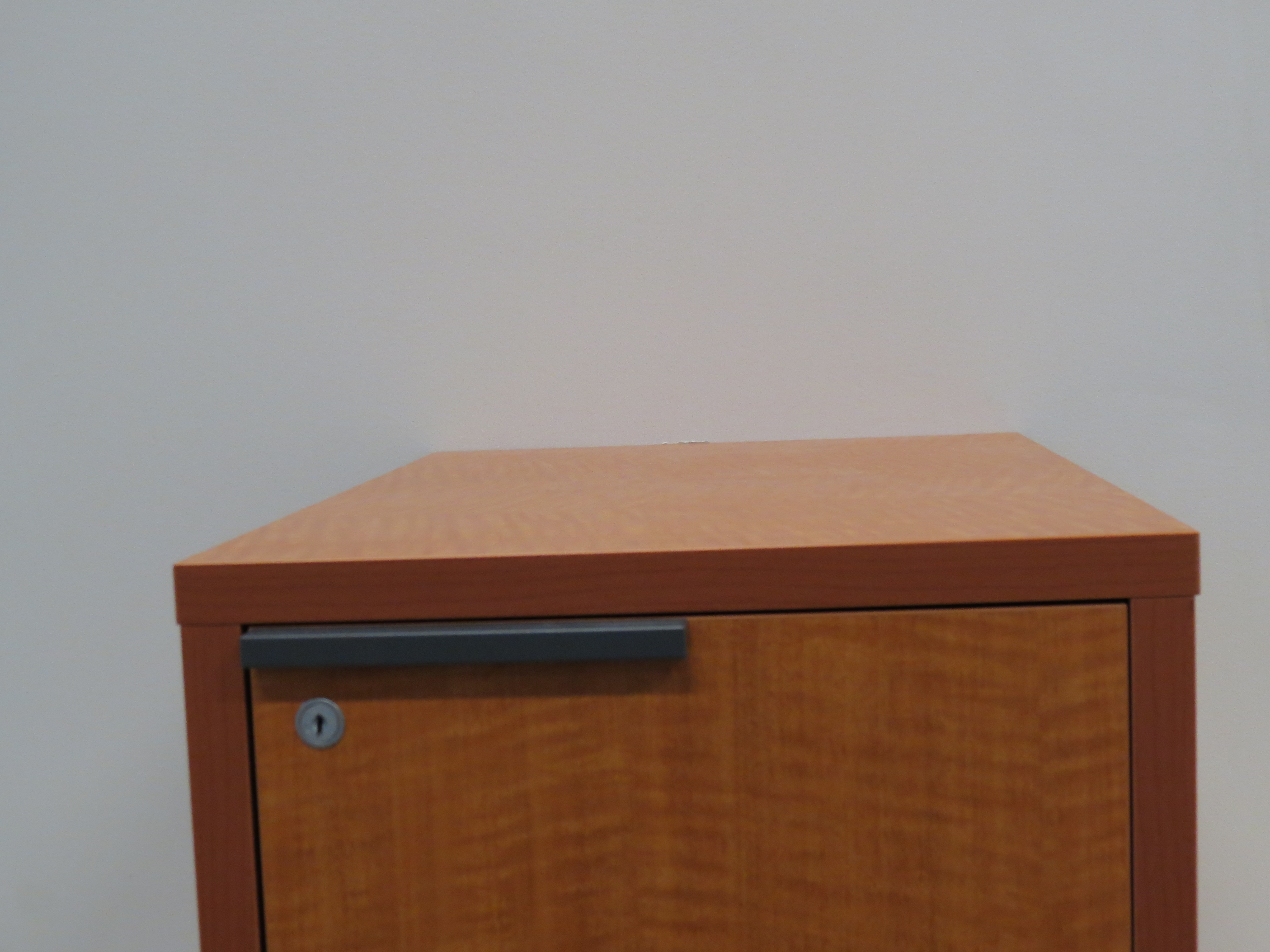
I composite the render objects scene, the empty scene, and the background image by using the masks. Finall results are shown in below:
| Background image | Finall result |
 |
 |
 |
 |
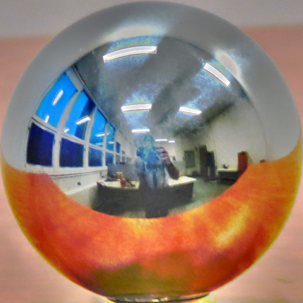
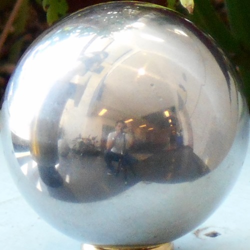
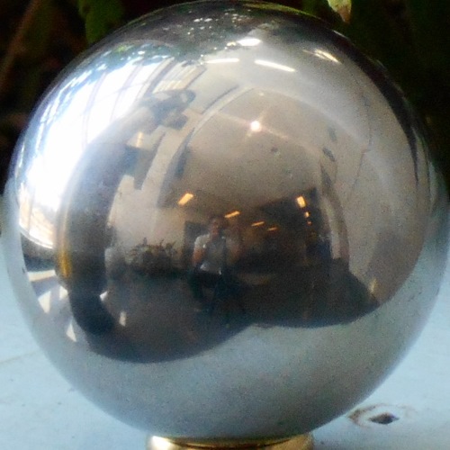
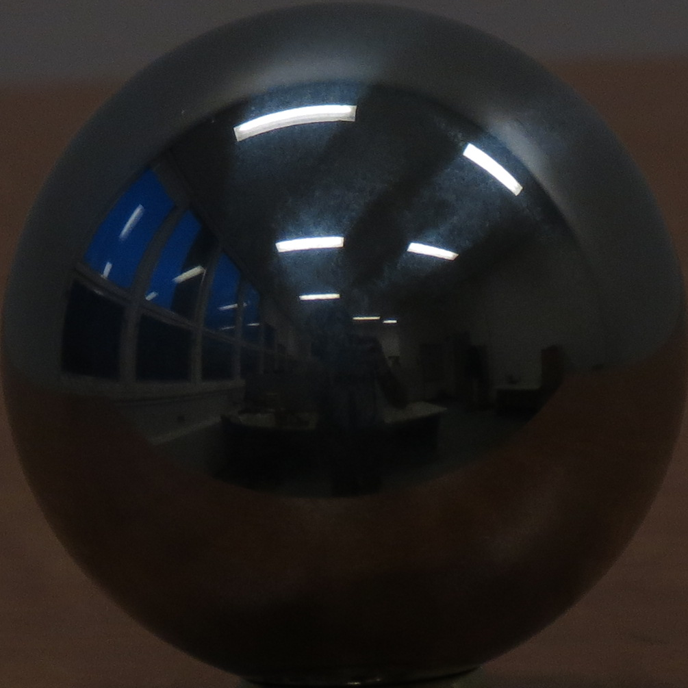
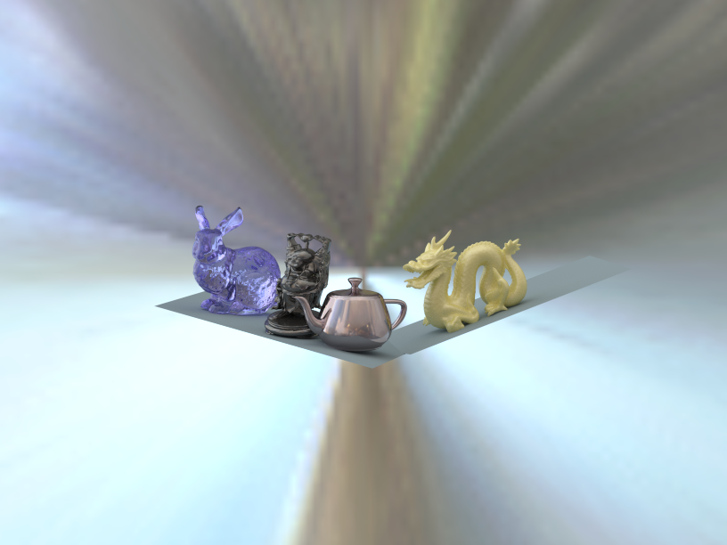
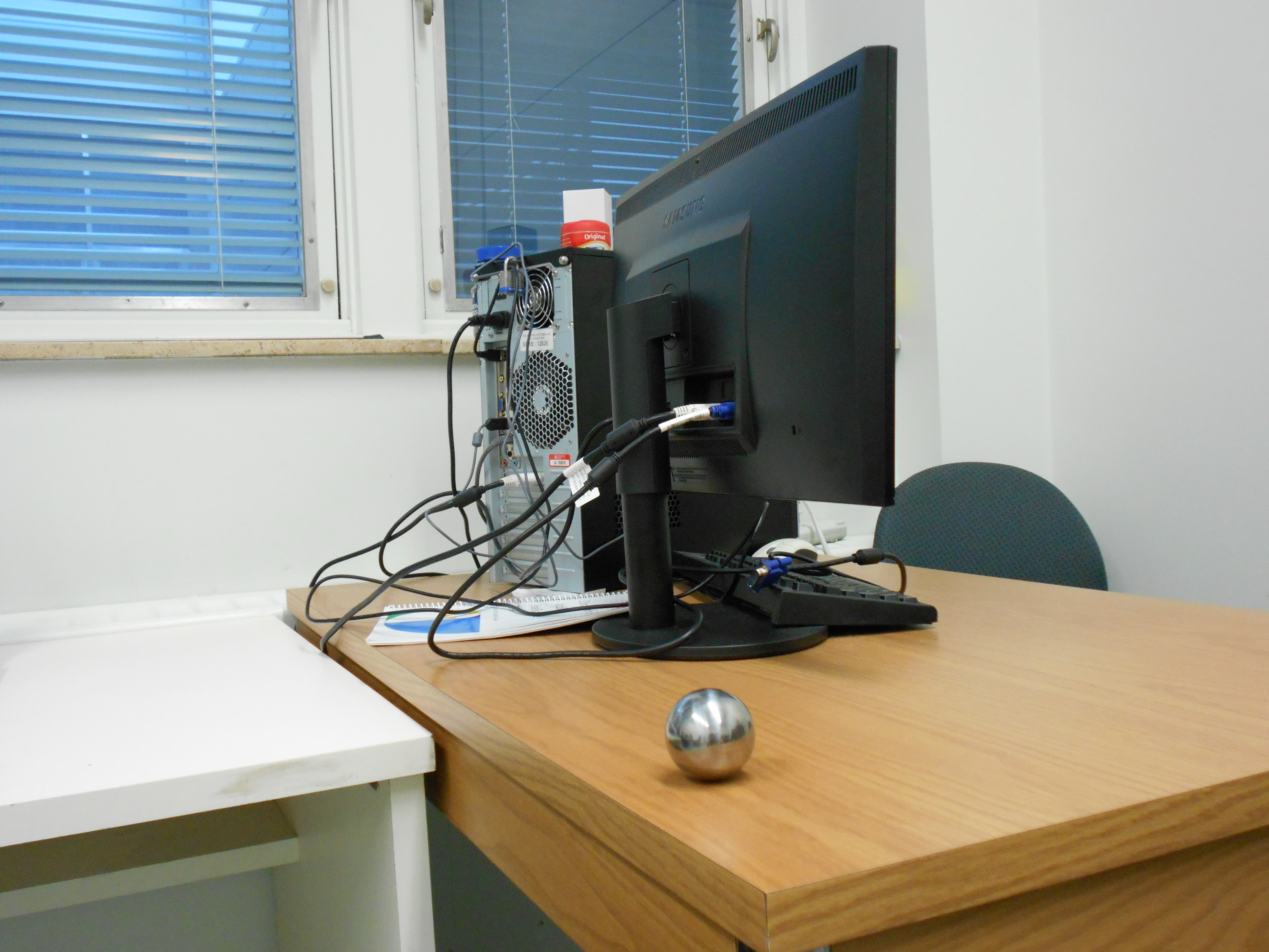
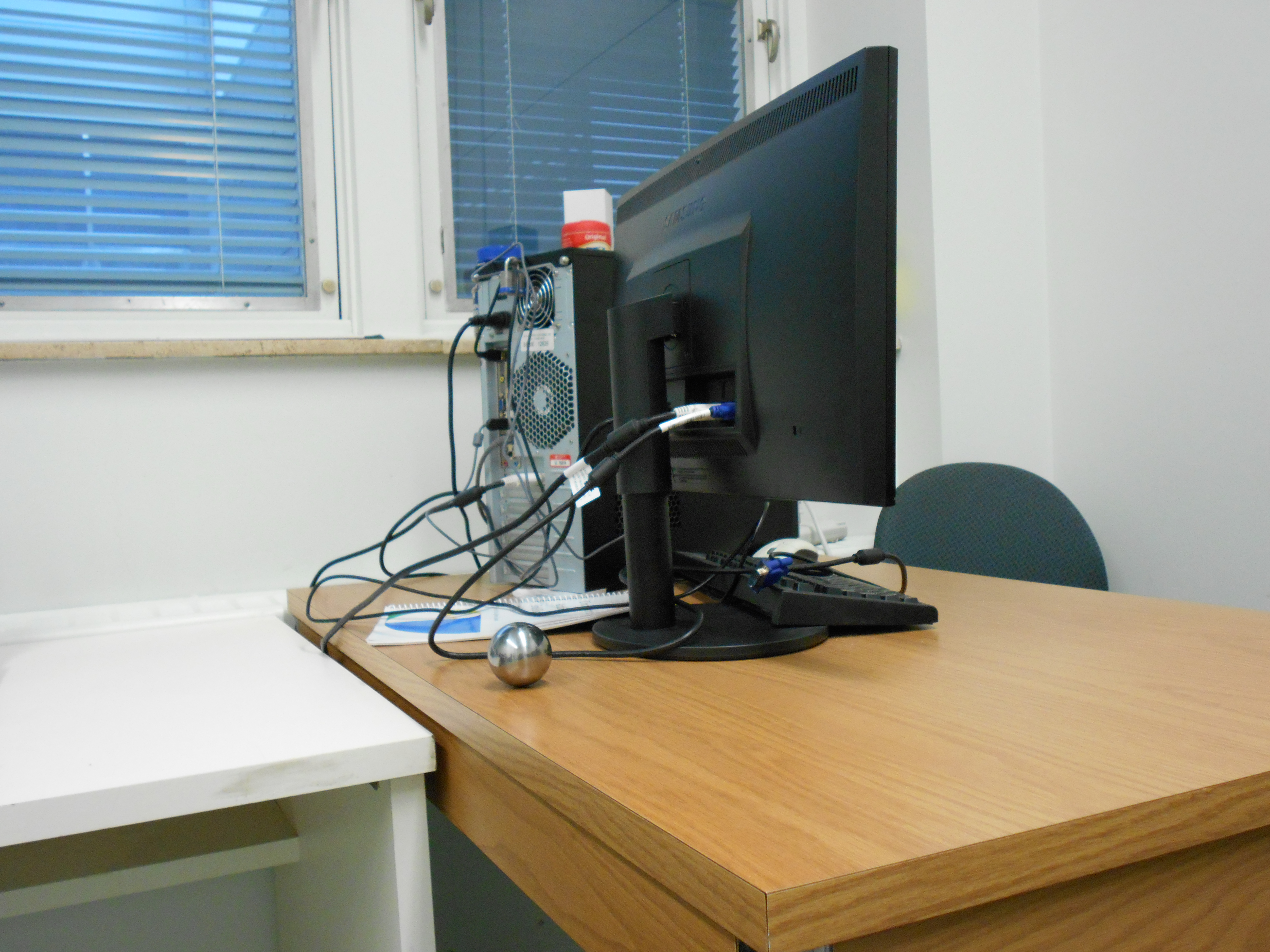
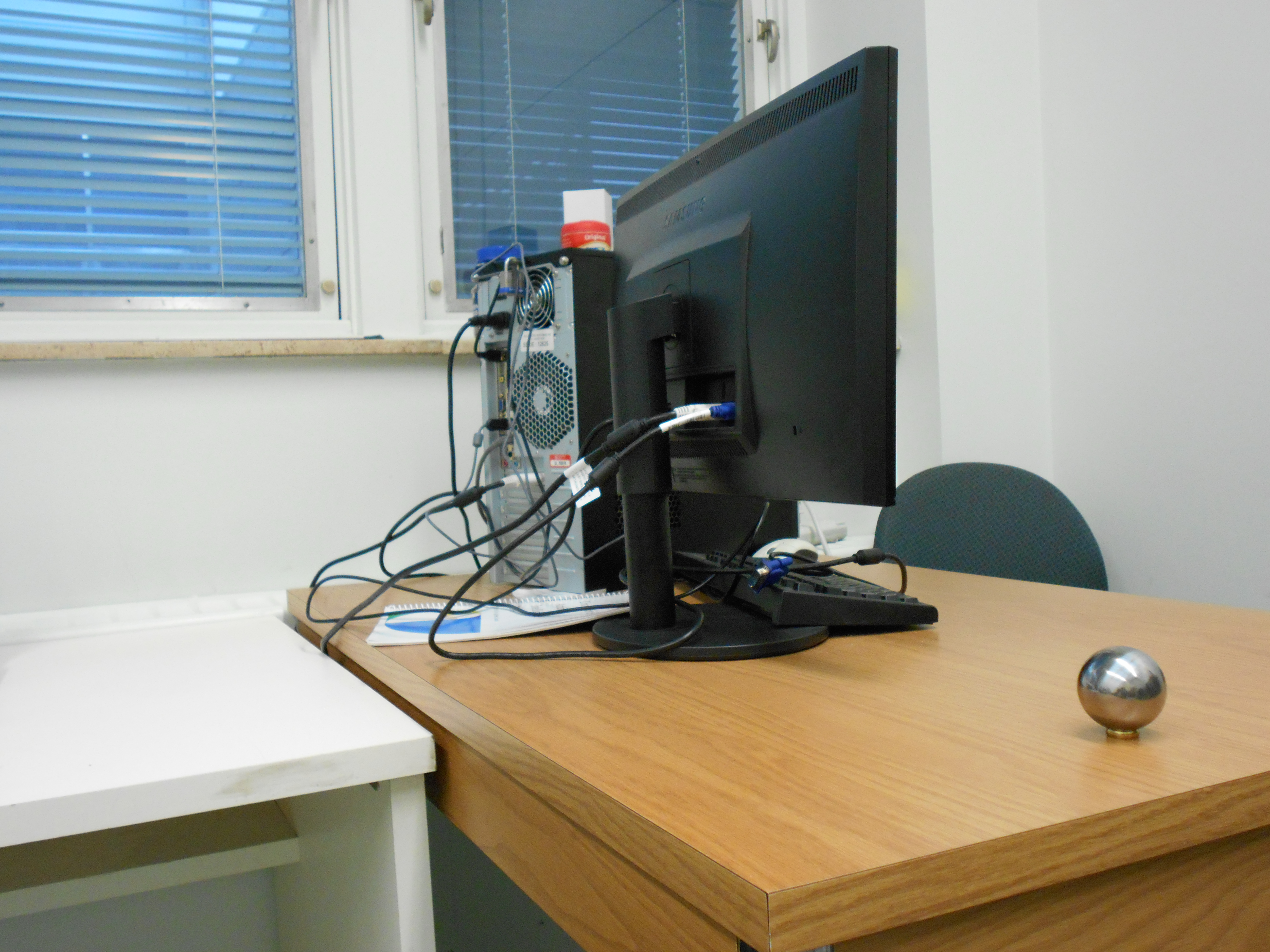
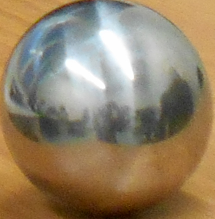
For best result of relighting virtual objects based on the rectiangular HDR image, the objects should be placed in the near of the real mirror sphere, not to far away from it, or in other direction that photo is taken. Let me explain this in the following example. In the following pictures, I took several pictures from a constant view point, but move the shpere. As you can see, the light information is changed in sphere 4. But when I used in the Blender, and put objects in different direction, the same light information is used to relight all the objects! Therefore, the render objects should not be very realistic, when I put an object that it is near the real mirror sphere, while is in different direction!
| 1 | 2 | 3 | 4 |
 |
 |
 |
 |
 |
 |
 |
 |
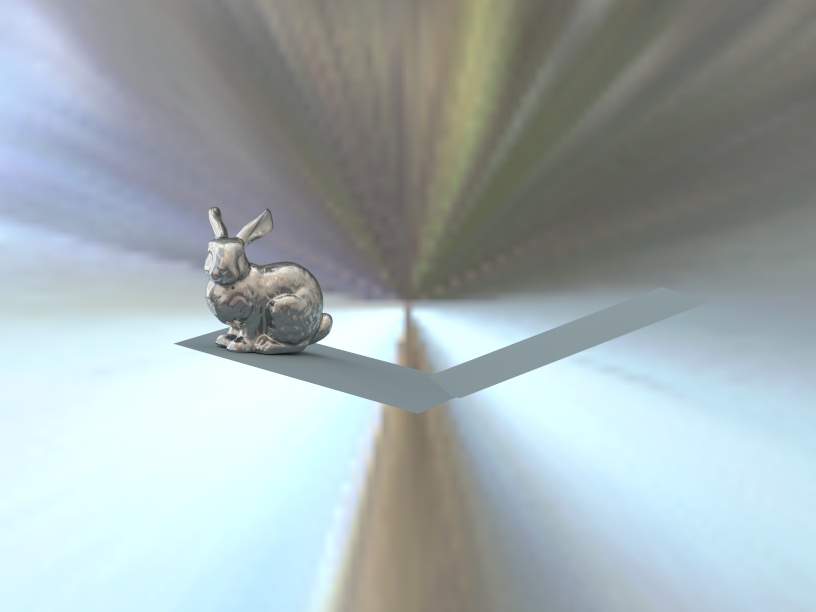
I try to show this effect when relight objects by the same light information in Blender. As we can see, the left sphere has correct light information, while this light information for the most right sphere is not realistic. Therefore, Bunnny is relighted correclty, while dragon has not realistic light information
 |
 |
 |