TP5: Insertion of virtual objects
by Cédric Tremblay
High Dynamic Range radiance map
First and foremost, in order to realistically insert virtual objects into a photograph, we need to extract the lighting
environment from where the image is taken. This is done so that we can later light our objects as if they
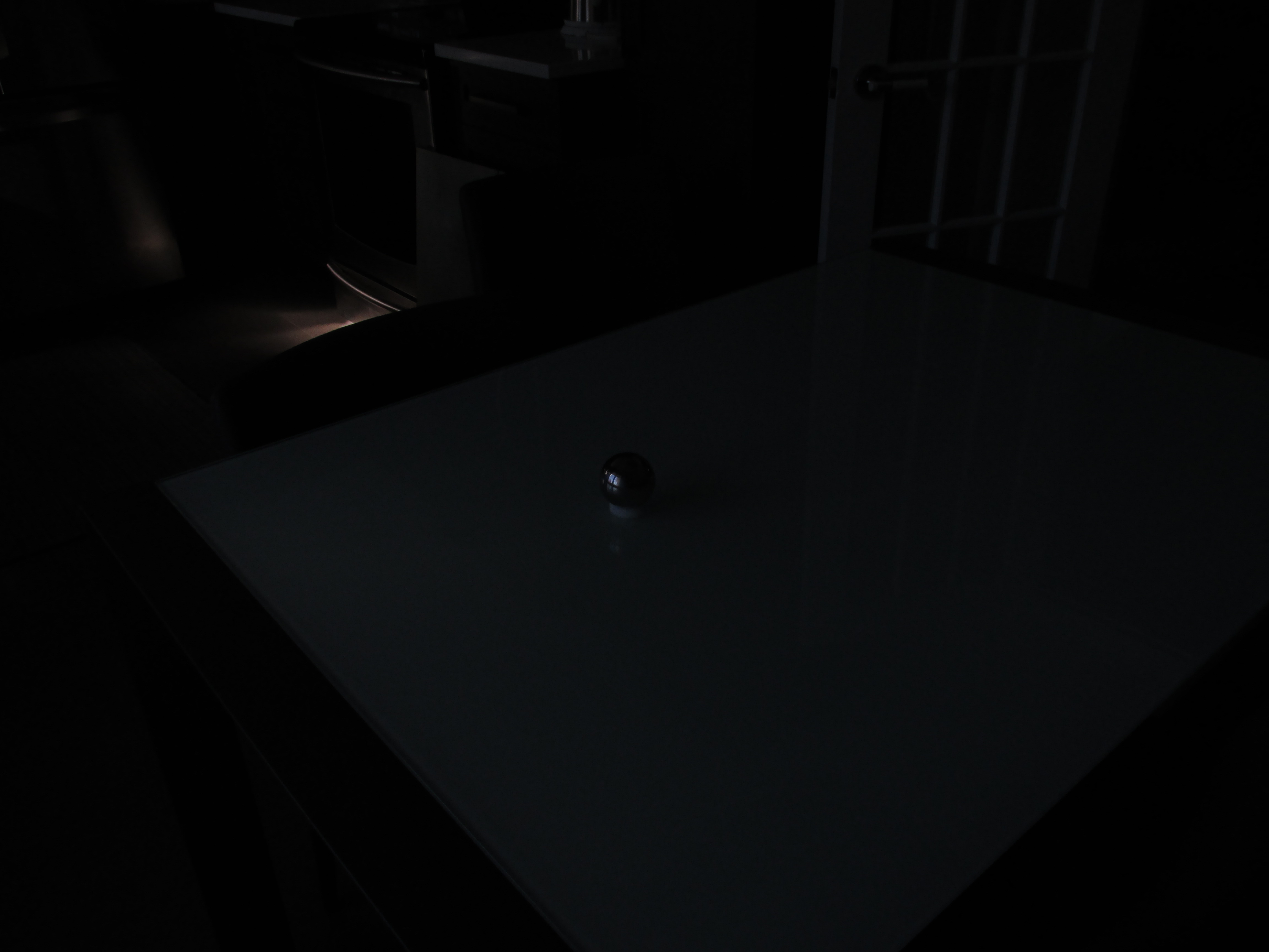
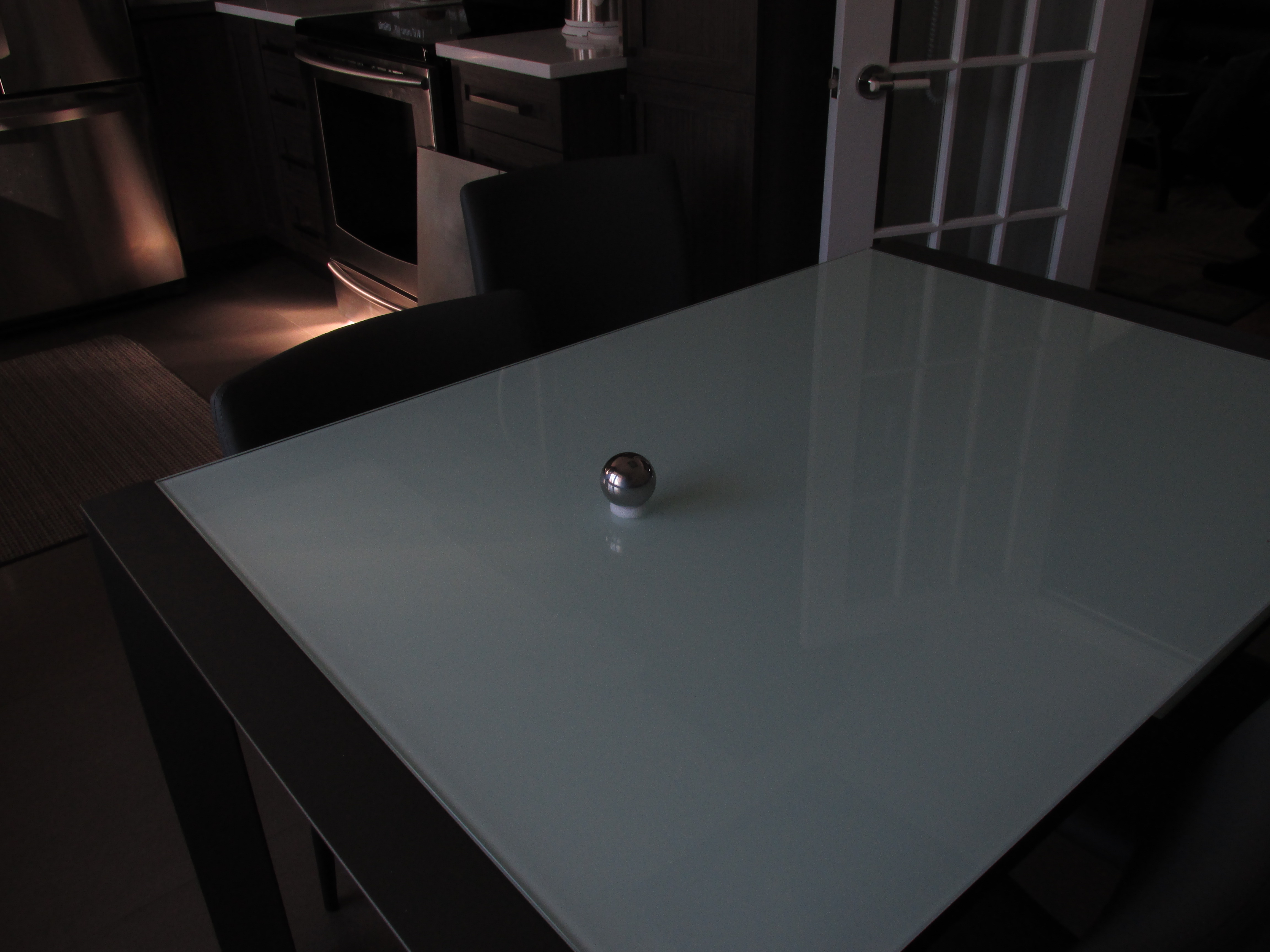
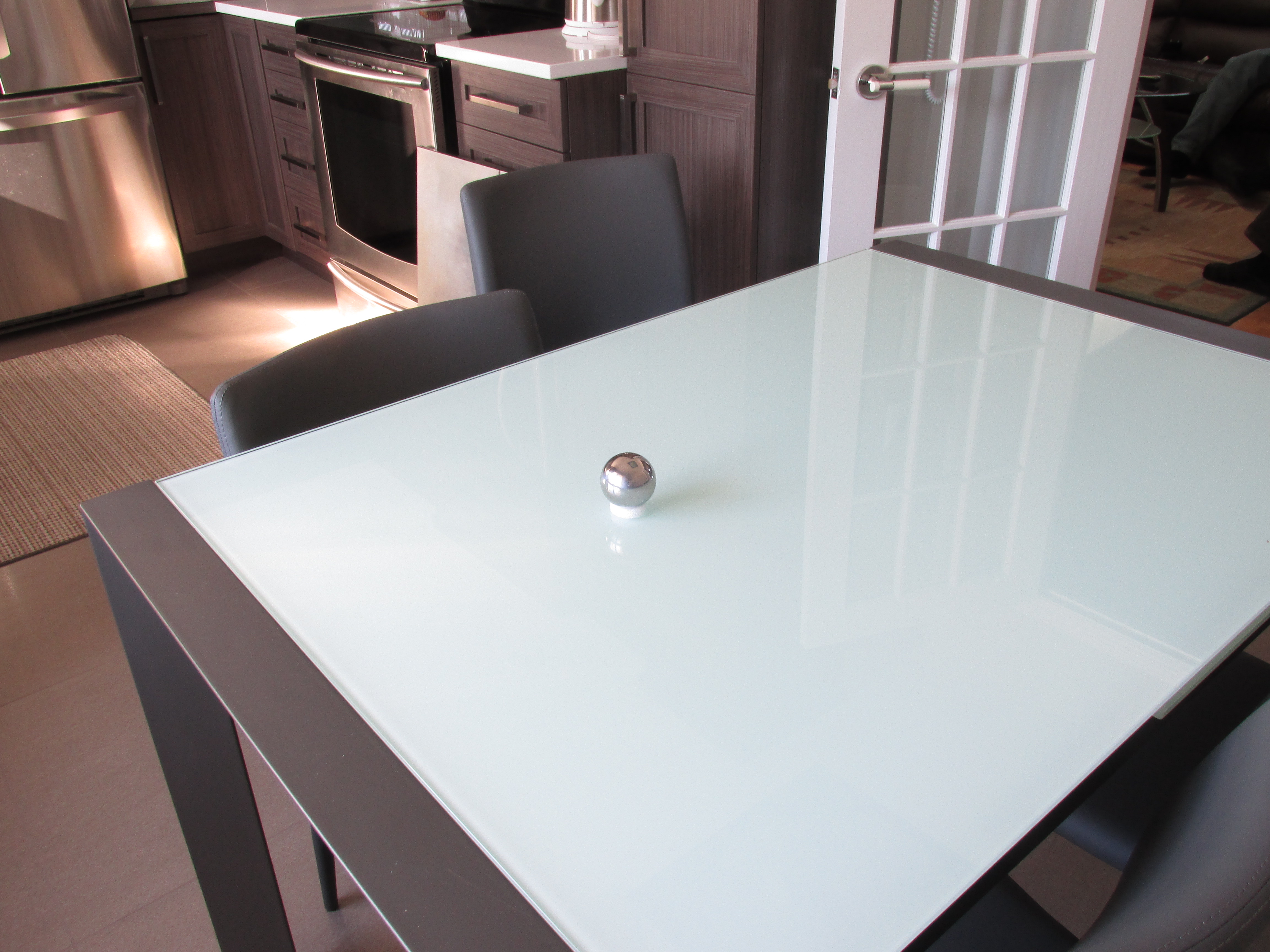
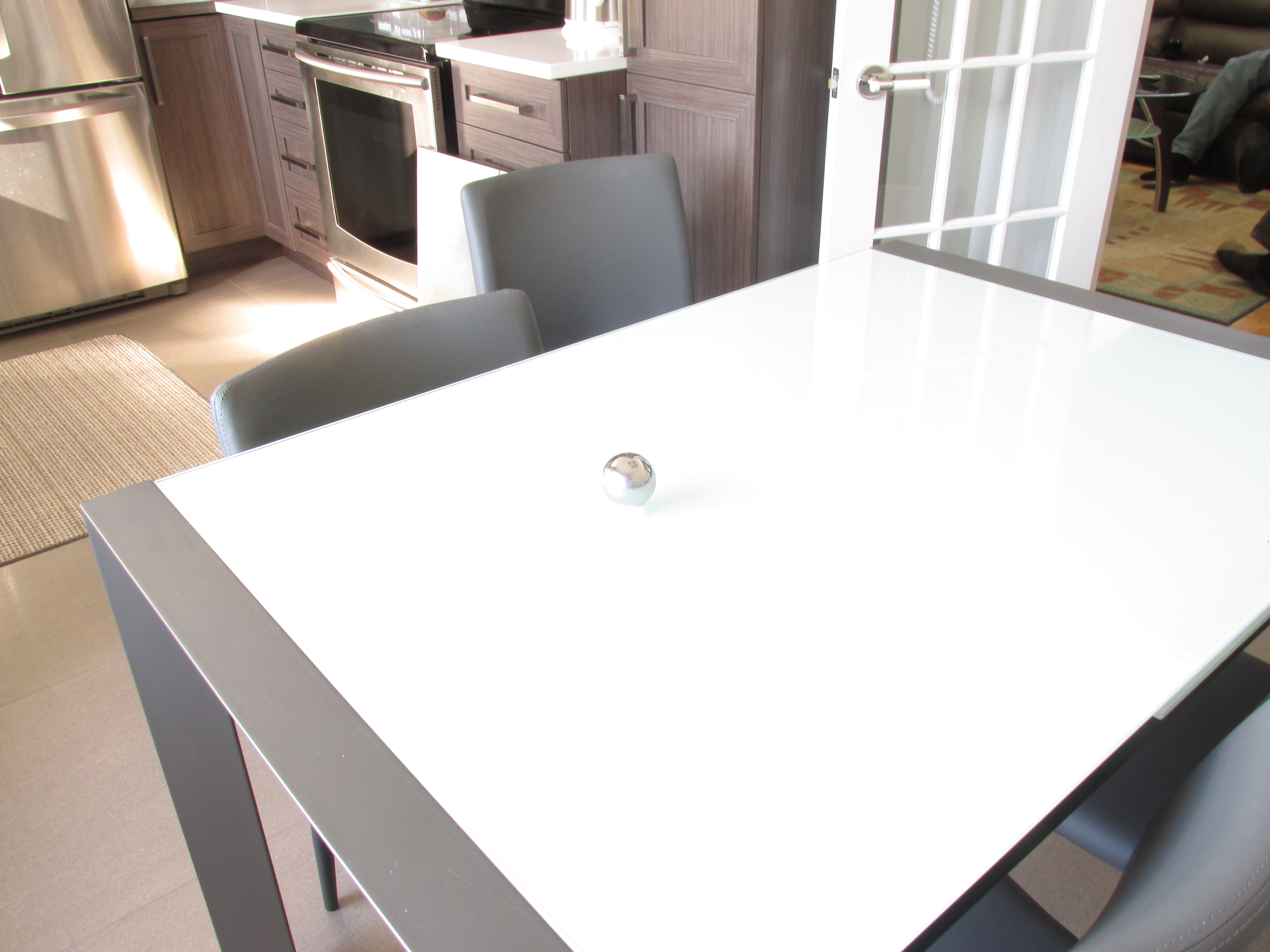
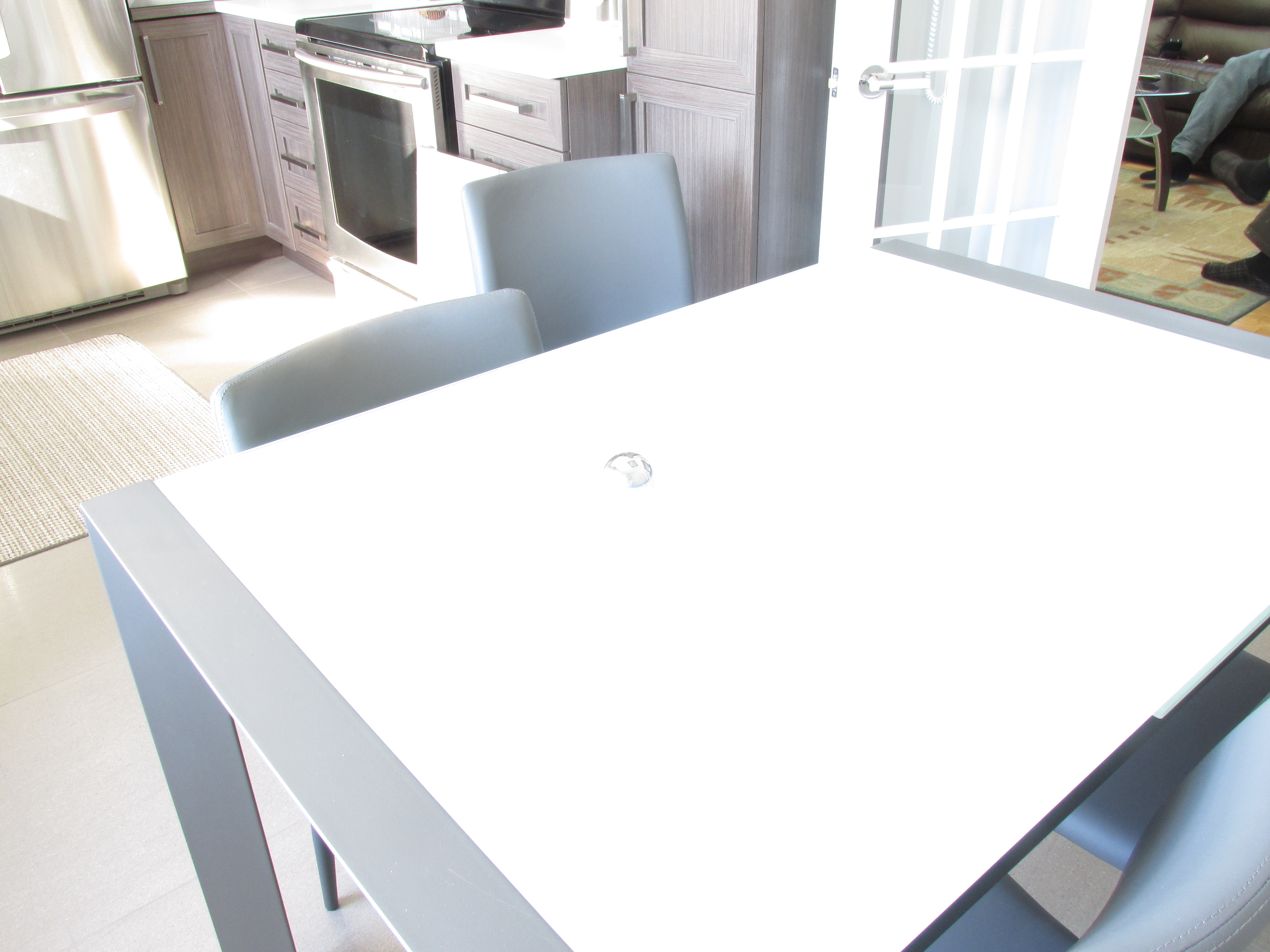
were present at the moment the picture was taken. To capture the lighting of the scene we use a spherical
mirror because it is able to map the light information coming from every direction unto its surface.
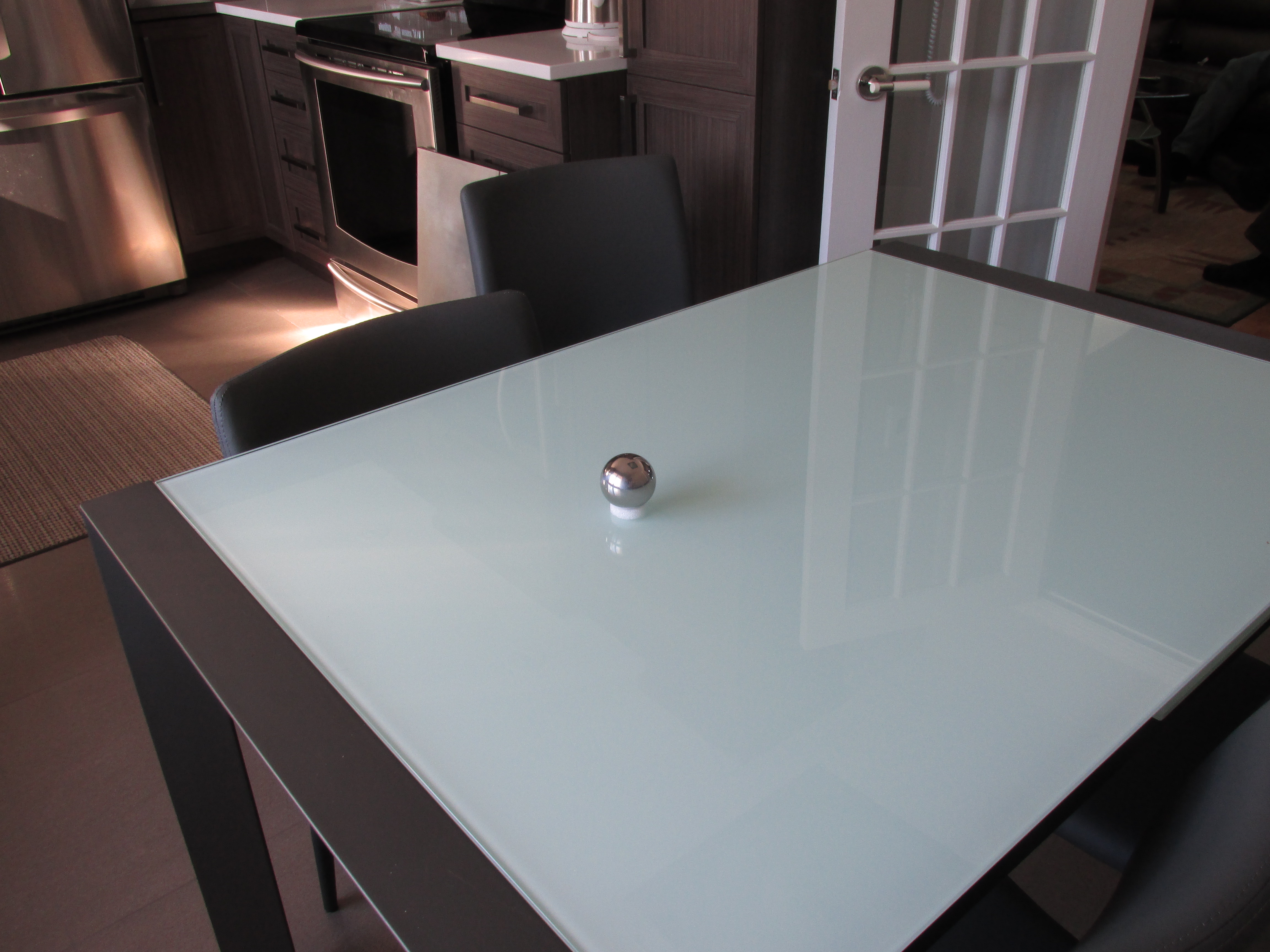
Furthermore, in order to capture all the nuances of the lighting, we will create a High Dynamic Range radiance map. This is achieved by taking
several pictures of the same scene using different exposure times, this allows us to better capture the true intensity of the light present in the scene.


What we want to do with these images is get the 'radiance' from each pixel, where the radiance is defined like so:
Ei = exp(∑[j=1 to P](w(Zij )*(g(Zij)-ln Δtj ) / ∑[j=1 to P](w(Zij))
where E is the radiance value for pixel i, Z is the intensity of pixel i in picture j, P is the number of pictures
, w(z) is a triangular function with a slope of 1/128 and g(Z) is the function lnƒ-1 where Zij=ƒ(Ei*Δtj)
From these Low Dynamic Range images we then use the algorithm described by Debevec and Malik in their
1997 paper to
compute the 'g' response curve for the RGB colour channels and then solve the preceding equation for each pixel of our image.

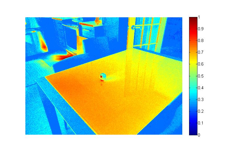
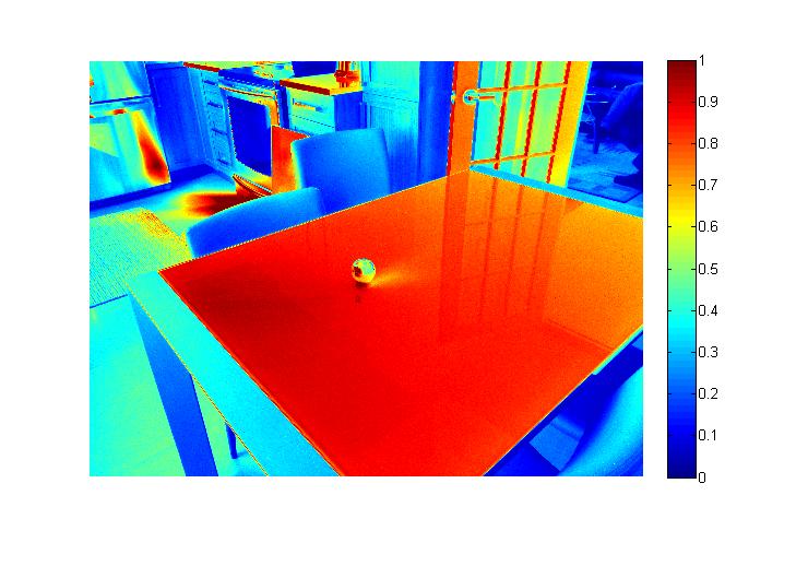
The resulting radiance map has values much higher than the 8-bit 255 limit of a standard RGB colour image, so in order to display it
we normalize it using the Reinhardt operation with a 0.2 scale factor: pixel_intensity = 0.2*Ei/(1+0.2*Ei)
The left image is this normalized radiance map represented with false colours and the image on the right is a regular image with correct
exposure time, we can easily see that there is much less saturated pixels in the HDR map than in the normal image.
Equirectangular transformation
Now that we have our radiance map we need to transform it to a panoramic 360 degree view so that it can be processed by a render engine.
We start by selecting only the section of our radiance map that contains the sphere and we unwrap the sphere unto a rectangular plane. This is
done by using the Cartesian coordinates of each pixel on our sphere and transforming them to spherical coordinates. To do this we assume the z-axis
points up, the y-axis points right and x-axis points towards the camera, we normalize z and y to the range [-1,1] and then use the equation of a sphere
to get the x coordinate: x = sqrt(r2-y2-z2) with r=1. All those resulting coordinates are the normal vectors of every pixel
of the sphere. Now, since we want to create a panoramic view of the environment we need to know where each light vector hitting the sphere and reaching
the camera originates from. Since we chose the x-axis as pointing towards the camera, we know that every reflected light ray that reaches the camera has a vector
of [1,0,0]. To find where that light ray comes from we use 'vision vectors' of [-1,0,0] which will go from the camera to the point in the real world.
Knowing both the normal and the incident vector of every pixel it is easy to find the reflected ray simply by subtracting the projection of
the incident vector unto the normal to the incident vector twice: reflected = incident - 2*(incident • normal)*normalized normal
We then convert the Cartesian coordinate of the reflected vectors to spherical coordinate using the equations:
φ = atan2(z,√(x2+y2))
θ = atan2(y,x)
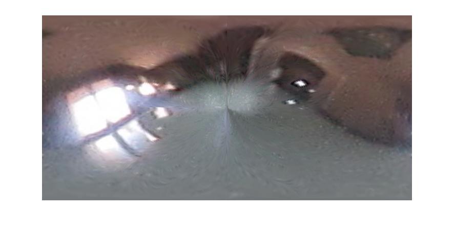
We then associate the Cartesian pixel values to their corresponding spherical coordinate and finally interpolate pixel values to
fill our new (-π/2:π/2)X(0:-π π:0) equirectangular image, with column representing θ values and the rows being the φ values.
The left of the rectangle corresponds to the front left side of the sphere, the middle corresponds to the back of the sphere and
the right side corresponds to the front right side of the sphere.

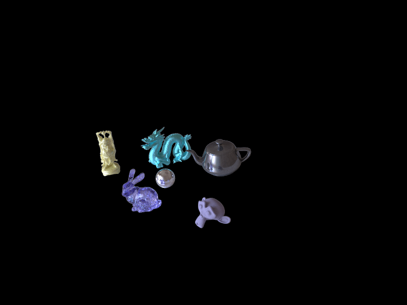
Render objects
For this project, Blender 2.74 was used to render the objects unto the photographs and our equirectangular HDR radiance map
was used as light source. A plane was used to simulate the table on which the object rested. Since the table is made of white glass
the material of the plane had to be able to show shadows as well as the reflection of the objects unto the table, so a mixed shader
was used with both having a weight of 50%, the first was a Glass material with an IOR of 0.85 and the second was a white Diffuse material.
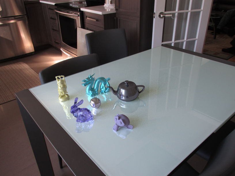
In order to make this image we first needed to render the object resting on their plane, then we render the plane by itself and finally a mask of
the objects.
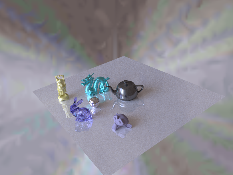


Then using the mask and the objects render we create an image containing only the objects. After we use the inverse mask to create the background
without the pixels where the objects will be. Finally, we subtract the plane to the object render and apply the inverse mask to only keep the
interaction between the objects and the plane. Using these three image, we can simply add them to create the result above.