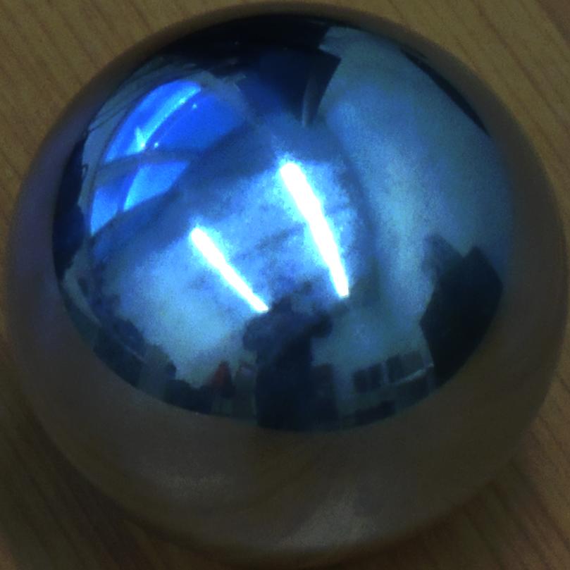
The final goal of this assignment is to insert a virtual (3d model) object into a picture, respecting the scene radiance and environmental lighting. Our main reference for this homework is Debevec1998 in which, the author uses a spherical mirror (light probe) to measure the scene’s radiance and global illumination in order to add new objects to light-based models with correct lighting [1].
We used Matlab and Blender to accomplish this assignment. The overall procedure could be described as below:
All these steps are fully described and discussed in this report and some results are presented at the end.
According to Debevec1997 [2] we have to take several LDR photos with different exposure from a stationary scene in order to generate an HDR image in which, each pixel’s intensity is directly proportional to the actual radiance value of that point in the scene. For this homework I took 6 photos from each scene first without the light probe and the other five with it; one with exposure value of 0, two with stop values of +1 and +2 and the last two, with -1 and -2 stop values. These values are just stop numbers, we are going to need true exposure times to use this method. In my case the exposure times were: 1s, 0.5s, 0.25s, 0.125s, 0.0625s.
I also had to choose the distance between camera and the metallic ball wisely, i.e. far enough to have a relatively good orthographic camera but not too far, to lost a good view of the metallic ball. The mirror ball should take at least 256x256 pixels of our image.
After taking our photos, we have to crop the mirror ball out of each image and align it perfectly in each cropped image. I specifically paid attention to take a rectangular crop out of each image, this way I could easily use a sphere equation (![]() ) to take the actual sphere pixels into account, later in my code.
) to take the actual sphere pixels into account, later in my code.
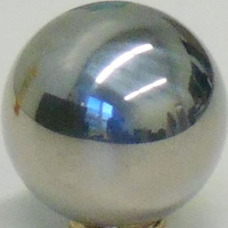
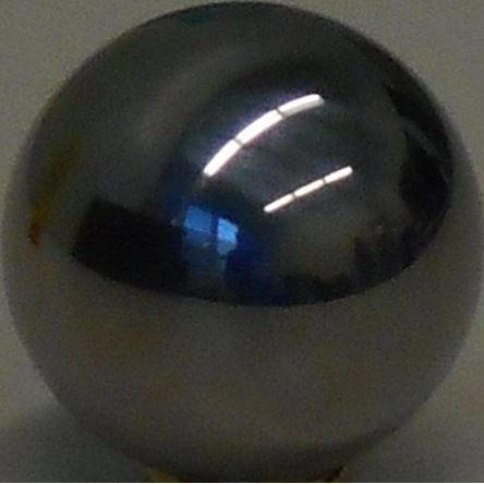
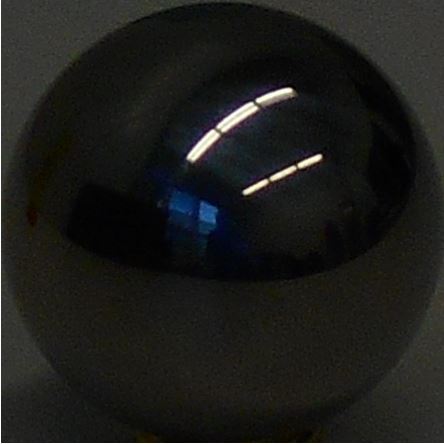
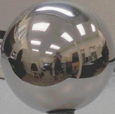
Here are the cropped light probe pictures of my first scene (Click for larger images):
 |
 |
 |
 |
 |
Exposure Value = +2 |
Exposure Value = +2 Exposure Time = 0.5 s |
Exposure Value = +2 Exposure Time = 0.5 s |
Exposure Value = +2 Exposure Time = 0.5 s |
Exposure Value = +2 Exposure Time = 0.5 s |
Measuring the actual amount of light in a scene is difficult because of the wide range of brightness from very bright light sources to very dark corners of the room. As a matter of fact, the intensity of a light source is two to six times larger than the intensity of the non-emissive parts of an environment [2].
However we have to capture all this range if we want to have an accurate radiance map of our environment. Here we assume that all the pictures are taken from a static scene and during a reasonably delay so the changes in the lighting could be ignored, this way we could assume that the radiance of each pixel remains the same in the obtained images.
We assume the intensity of each pixel in the image is a function of the irradiance of that pixel and the integration time of the sensor (exposure time):
![]()
Where i is the pixel index in each image, j is the number of the image (here between 1 to 5), Zij is the intensity of the i th pixel in j th image, Ei is the radiance of the i th pixel and ![]() is the exposure time of the j th image.
is the exposure time of the j th image.
Since we need to calculate radiance from intensity, we have:
![]()
And to make the equation linear:
![]()
We now have to calculate g which is a difficult task as Ei is an unknown parameter. However we can assume that Ei is consistent in all pictures. On the other hand, Z (intensity) can only have discrete values (0 to 255). So by selecting N pixels from each of the obtained images which have the same Ei (all N points have the same position in the image so they have the same Ei) we could use least square approach to minimize the following expression to find discrete values of g:
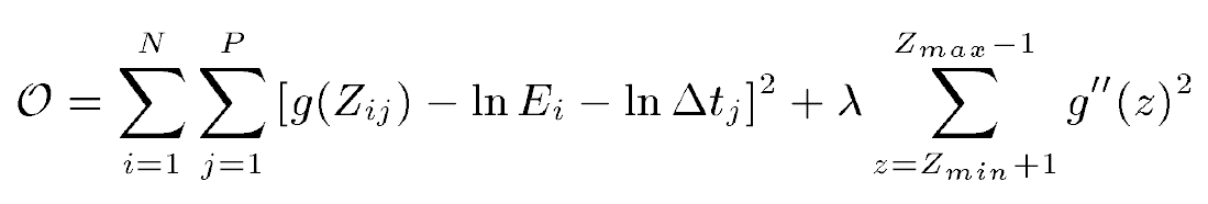
The second term of the above equation makes sure that the obtained g is a smooth curve. Lambda could have different values, I started from 1 and went upward till I got a smooth curve for g.
In order to calculate ln E I used the Matlab function provided by the author of the article. This function uses the equation below:
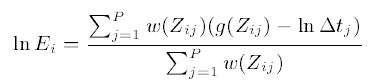
As can be seen we have to provide the above-mentioned function with a weight function w which is also given in the article.
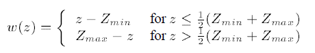
I used the function handler w = @(z) double(128-abs(z-128)) that generates the same result as the above equation.
Note that the mentioned function calculate ln E and not the actual radiance (E), therefore we have to exponentiate the result to obtain the actual values of radiance.
At last we could use a simple Z = Z ./ (Z+1) equation to be able to show the final HDR image.
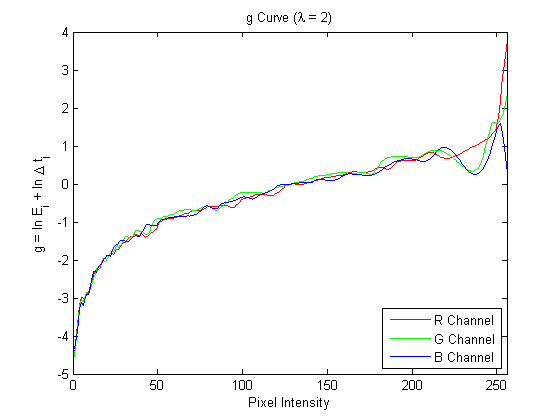
I applied the mentioned algorithm on all three channels of my images and obtain this curves for g (N = 100):
And here is my final HDR image of the metallic ball:

I have also applied the alorithm on the resource pictures given by our lecturer, here is the result:
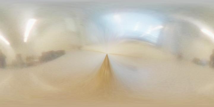
In order to use this radiance map for relighting, we are going to convert it to an acceptable format to almost all 3d modeling softwares, an Equirectangular (Latitude / Longitude) map. You can find a very good introduction of many of the other formats here.
In order to have a better understanding let’s take a look at our overall geometry:

As can be seen, we assume that we have an orthographic camera, i.e. all viewing rays are parallel and in the same direction. It also can be seen that the reflection vectors are computable having a static viewing vector and the normal vector in the point of incident and vice versa.
The reflection vectors can be calculated using this:
R = V - 2 .* dot(V,N) .* N;
And in reverse, normal vectors can be calculated simply by using this:
N = (V - R) ./ 2;
Now assuming our mirror ball as a unit radius sphere (with r = 0 in the center of the image and r = 1 at the edge of the sphere) the normal vector of each pixel of this sphere can be calculated. As it was mentioned above we can calculate the reflection vector having the normal and viewing vectors.
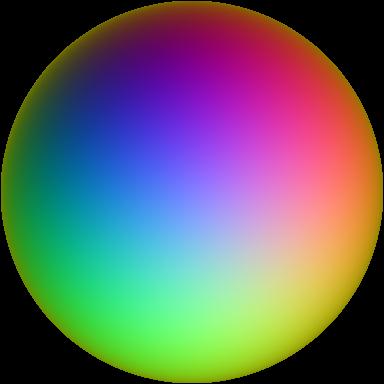
A lat/lon map is a rectangular image in which rows correspond to θ and columns correspond to φ in spherical coordinates. While –π < φ < π and – π/2 < θ < π/2.
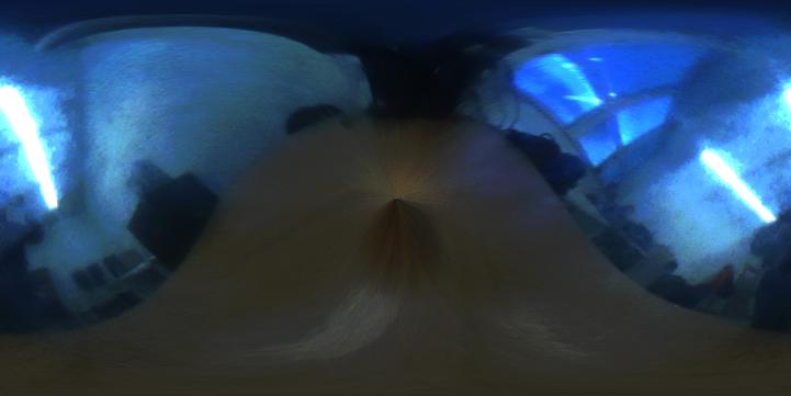
Now that we can assign each φ and θ to a specific x and y in the image, we can use interpolation to generate our euirectangular map. (I used interp2 function in Matlab). Here are the three environmental maps that I obtained for my scenes (Click for larger images):
|
 |
 |
 |
 |
 |
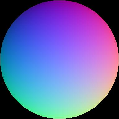
To make yourself more aquatinted with different maps take a look at these diagrams [3]:
 |
 |
 |
Normal Vectors |
Reflection Vectors |
φ and θ of the Reflection Vectors |
 |
||
Equirectangular map (rows : θ, columns : φ) |
||
The next step is to create a simple 3D scene in Blender which simulates a simple 3D model of our actual scene. This is my starting scene:
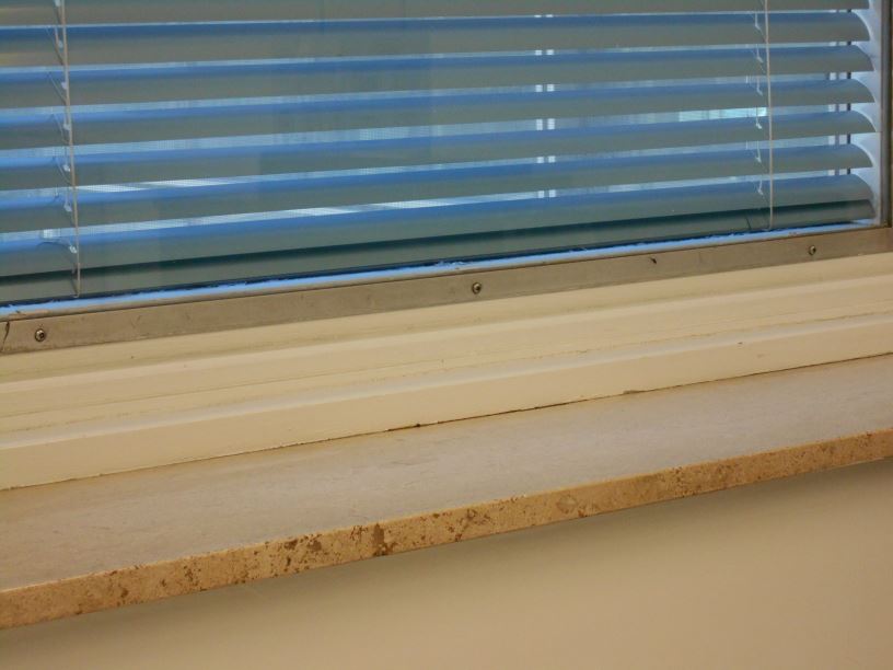
In order to do this part, we import the image of our scene (the one without the light probe) into Blender and we use it as a background for our camera viewport (In the middle panel check “Background Images” and import your scene using “Add Image” button). Like the picture below (Click for larger version):

In the shown picture, you can see that I used two simple planes to represent the top shelf and the wall. I select a diffuse BSDF as for their material and a color close to the actual surface color for them. We take a render of this scene before adding our models.
In order to align these planes with my scene I had to transform and rotate them a few times to have the best alignment. If we look at them from a global point of view (not the camera view) we will see something like this:

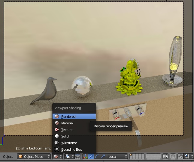
The next step is to set the obtained HDR image as an environmental texture. To do that go to “World” tab and under “Surface”, select “Environmental Texture” in front of “Color” and then select your image in the box below it.
After that if you change the “Viewport rendering” option to “Rendered” you can sneak a fast peek to your result very quickly and see the reflection of the environment on your shiny objects!
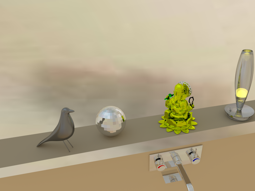
As can be seen I have added several models to my scene and used different material for them. Here are a simple table of my objects materials:
Model |
Material and properties |
| Black Bird | Shader: Glossy BSDF (GGX), Color: Grey, Roughness: 0.05, Normal: Default |
| UV Sphere | Shader: Glossy BSDF (Beckmann), Color: White, Roughness: 0, Normal: Default, Shading: Flat |
| Statue | Part 1: Glossy BSDF (GGX), Color: Yellow, Roughness: 0, Normal: Default |
| Part 2: Glossy BSDF (GGX), Color: White, Roughness: 0, Normal: Default | |
| Part 3: Refraction BSDF (Beckmann), Color: Green, Roughness: 0.033, IOR: 1.45, Normal: Default | |
| Part 4: Glossy BSDF (GGX), Color: Black, Roughness: 0, Normal: Default | |
Lamp |
Shader 1: Refraction BSDF (GGX), Color: White, Roughness: 0, IOR: 3.95, Normal: Default |
| Shader 2: Glossy BSDF (Beckmann), Color: White, Roughness: 0, Normal: Default | |
| Light Bulb (Inside theLamp) | Shader: Emission, Color: Light Yellow, Strength: 5.0, Normal: Default |
| Faucet | Shader: Glossy BSDF (Beckmann), Color: White, Roughness: 0, Normal: Default |
To have a decent scene with and robust results we blend our rendered scene into our actual scene using an alpha mask that we generate using Blender. To generate this mask, we need to first change the renderer to “Blender Renderer” (instead of “Cycles Renderer”, on top of the main window). We make a copy of our scene as we are about to change the materials of our objects.
Then we change the materials of all models to Diffuse BSDF with intensity of 1.0 and absolute white color. Don’t forget to check the “Shadeless” under shading options. After that we go to World tab and change the “Horizon Color” to black and then, we render the scene. Don’t panic! That is supposed to happen! Everything is in black and white, objects are shown by white and all the other stuff are just black.
Now we have 3 rendered images from our scene, one empty (just with surface planes), one with all of our models and planes and the last one is just a mask for our objects. We also have our background image (remember to resize it to the size of the other rendered images).

Just surface planes
Scene with models

Our object mask
We now blend our images using the equation below in Matlab:
composite = M.*R + (1-M).*I + (1-M).*(R-E).*c
Where,
M: Black and white Mask
R: Fully rendered image
E: Our empty 3D scene rendered image
I: Our background image
C: Controls the strength of lighting effects of the inserted objects (shadows, caustics, interreflected light, etc)
C = |
||
You can change the value of C and see the final result. (C=2 generates the best result). |
||
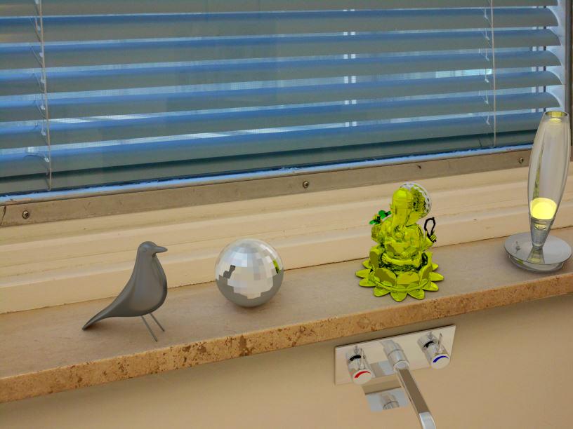
On the surface of the shiny objects of the scene, you can see not only the reflection of the environment (which we captured using Light Probe) but also the reflection of the nearby objects (Raytracing). You can also see the shadow of the faucet on the wall and the reflection of the bottom of the shelf on the faucet.
|
|
Final Result - Scene 1
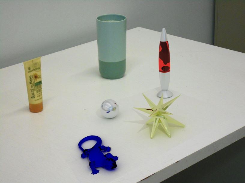
I applied the same steps on another scene. You can see the result here:
 |
 |
Final Result - Scene 2
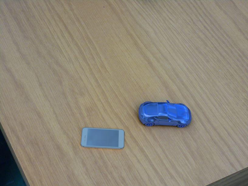
In this scene I left two other objects in the scene when I was taking my photos. As can be seen because of the lighting of the room, the shadows of virtually inserted images are different from the other two objects that was actually on the table. This can be corrected by inserting some simulated lights in the scene that we create in Blender. Therefore I just quickly add a spot light to the scene to see the result, just for fun!
The materials that I used in this scene are:
Model |
Material and properties |
| Lizzard | Shader: Refraction BSDF (Beckmann), Color: Blue, Roughness: 0.033, IOR: 1.45, Normal: Default |
| UV Sphere | Shader: Glossy BSDF (Beckmann), Color: White, Roughness: 0, Normal: Default, Shading: Smooth |
| Lava Lamp | Part 1: Glossy BSDF (GGX), Color: White, Roughness: 0.148, Normal: Default |
| Part 2: Glass BSDF (Beckmann), Color: Light Red, Alpha: 0.623, Roughness: 0.01, IOR: 1.8 | |
| Part 3: Diffuse BSDF, Color: Black, Roughness: 0, Normal: Default | |
Super star |
Shader: Glossy BSDF (Sharp), Color: Light Yellow, Alpha: 0.408, Roughness: 1.0, Normal: Default |
And a simple scene at the end:
 |
 |
 |
 |
 |