|
|
|
|
|
Project #4 : Image Stitching |
|
GIF-4105/7105 Photographie Algorithmique by Jean-François Lalonde
|
|
Submitted by: Razieh Toony
|

Project Overview :
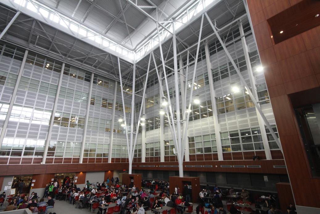
In this project, we are trying to create a panoramic photo by stitching together a bunch of overlapping and similar pictures together. In order to do so, given a pair of pictures, we define some correspondences between the pictures, find a warp homography matrix, register the two images together on a mosaic image, and blend them together. The projective transformation matrix can be solve by linear equations (SVD) which will be more explained in the following sections. Here , you can find a helpful tutorial of Image alignment and stitching.
Part 1: Manual matching
In order to make this simple process, we first accepted user's input as reference to the points we want to match. The idea is really simple, but we need a lot of work to manually assign the correspondence points. Since they are very sensitive, a better way is to have more points (7-8 pairs of points). Then we calculate the homography matrix based on these points. By using this homography, we projected second image on the first image coordinate system and merged them together to get the result.
Main steps,
· Collect correspondences (manually)
· Solve for homography matrix H ( Least squares solution )
·
Warp content from one image frame to the other to combine: (im1 into im2 reference frame)
- Determine bounds of the new combined image
- Attempt to lookup colors for any of these positions (You can use meshgrid in Matlab)
- Compute coordinates in im1’s reference frame (via homography) for all points in that range: H-1
- Lookup all colors for all these positions from im1 (You can use interp2 (Inverse warp) in Matlab)
· Stitch two images together (We can overlay im2 onto the warped image by using Max command in Matlab)
Hint :
(In the manually stitching we get number of refrence image as user defined input.)
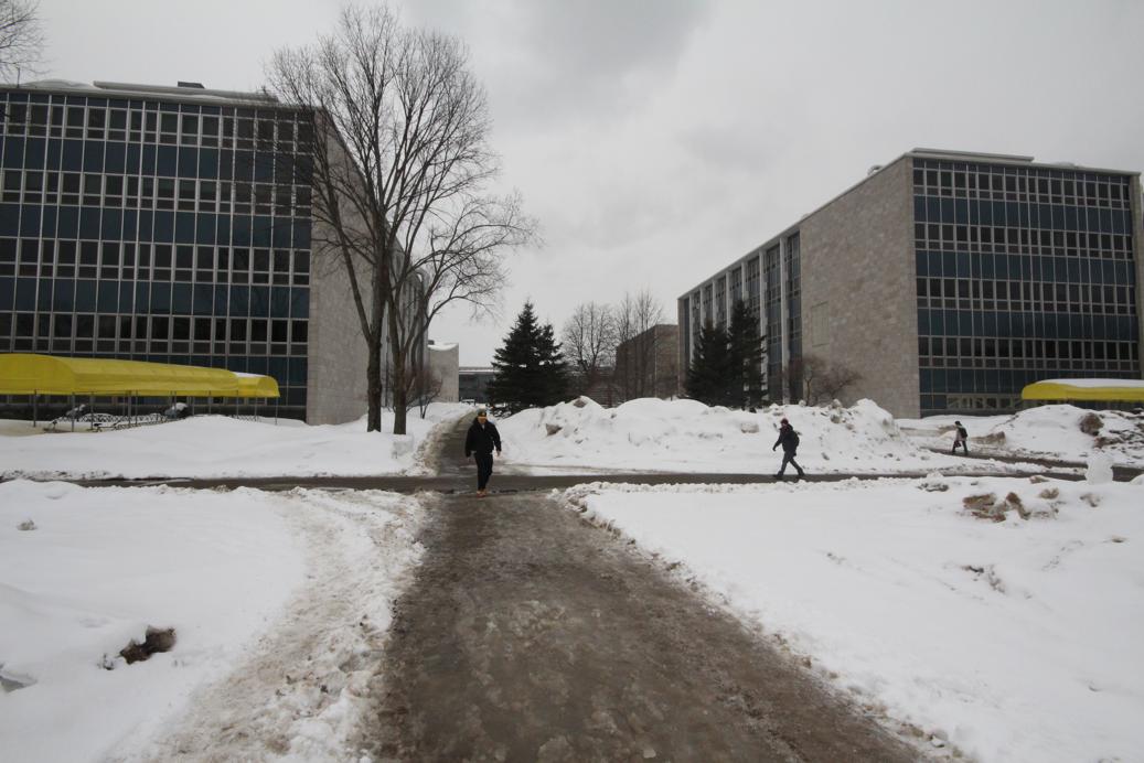
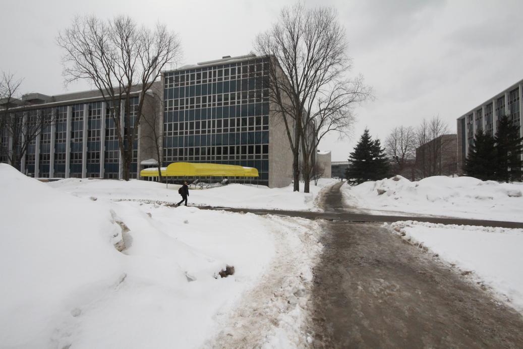
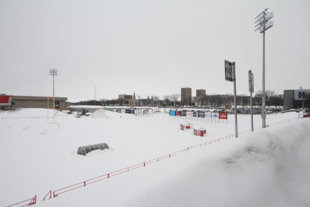
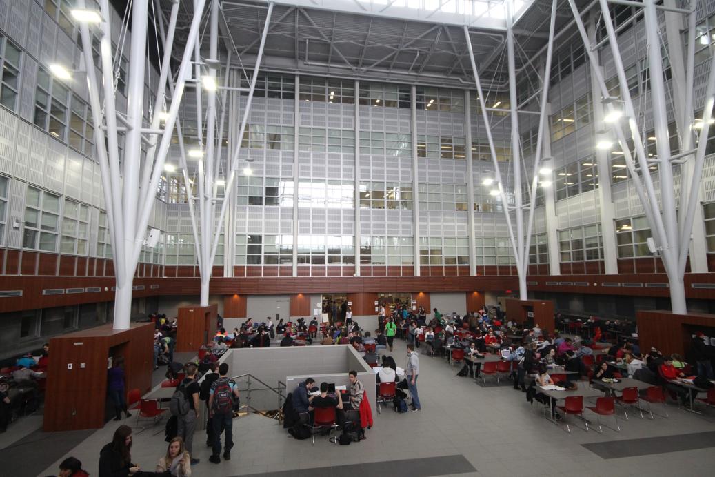
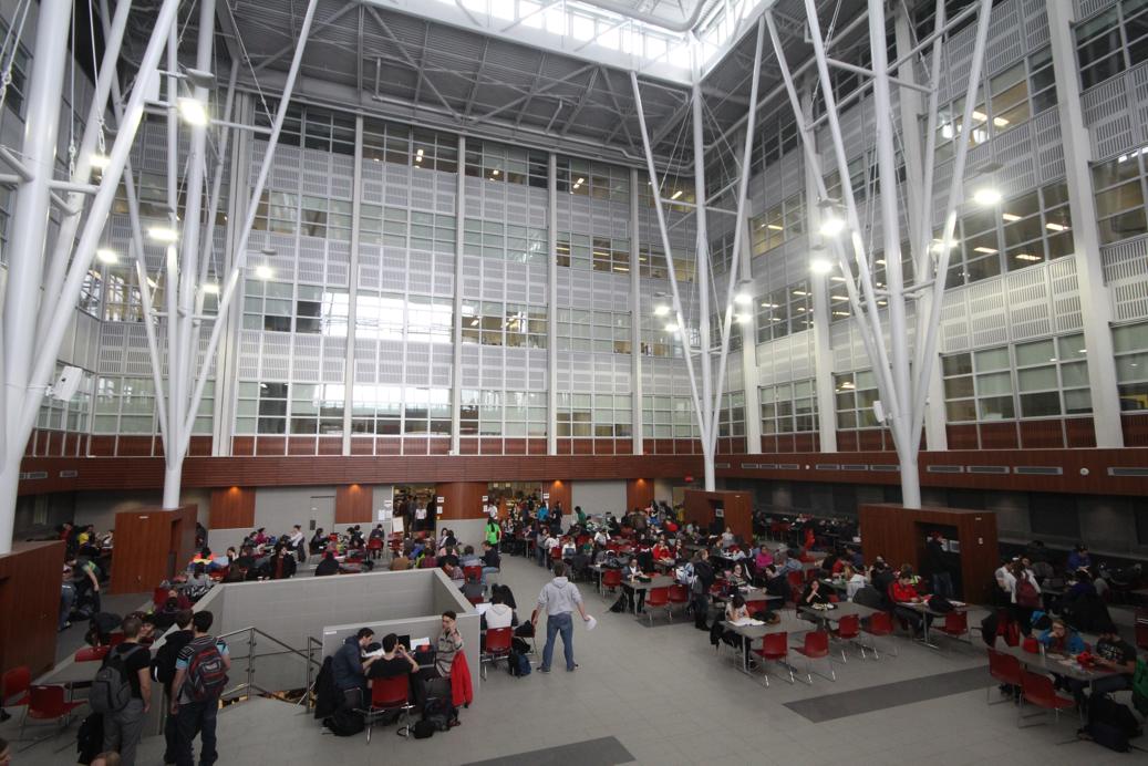
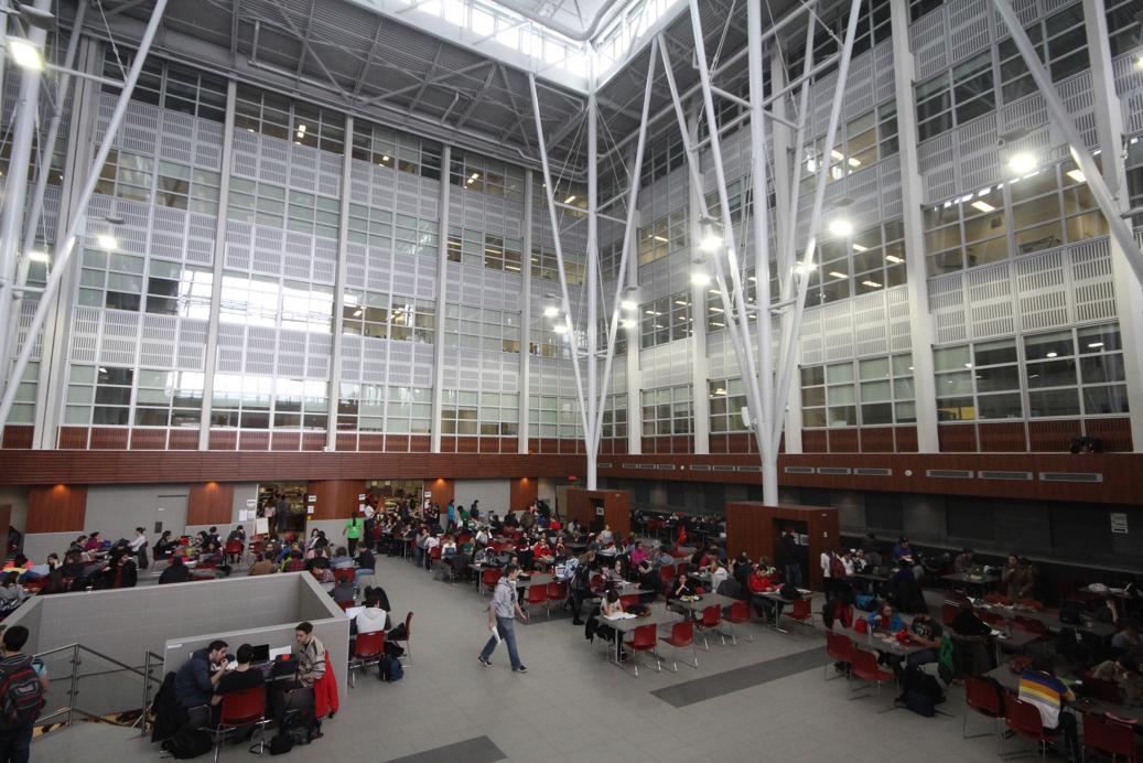
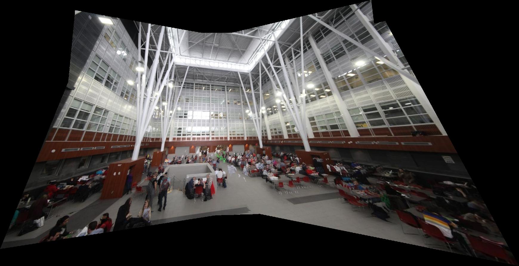
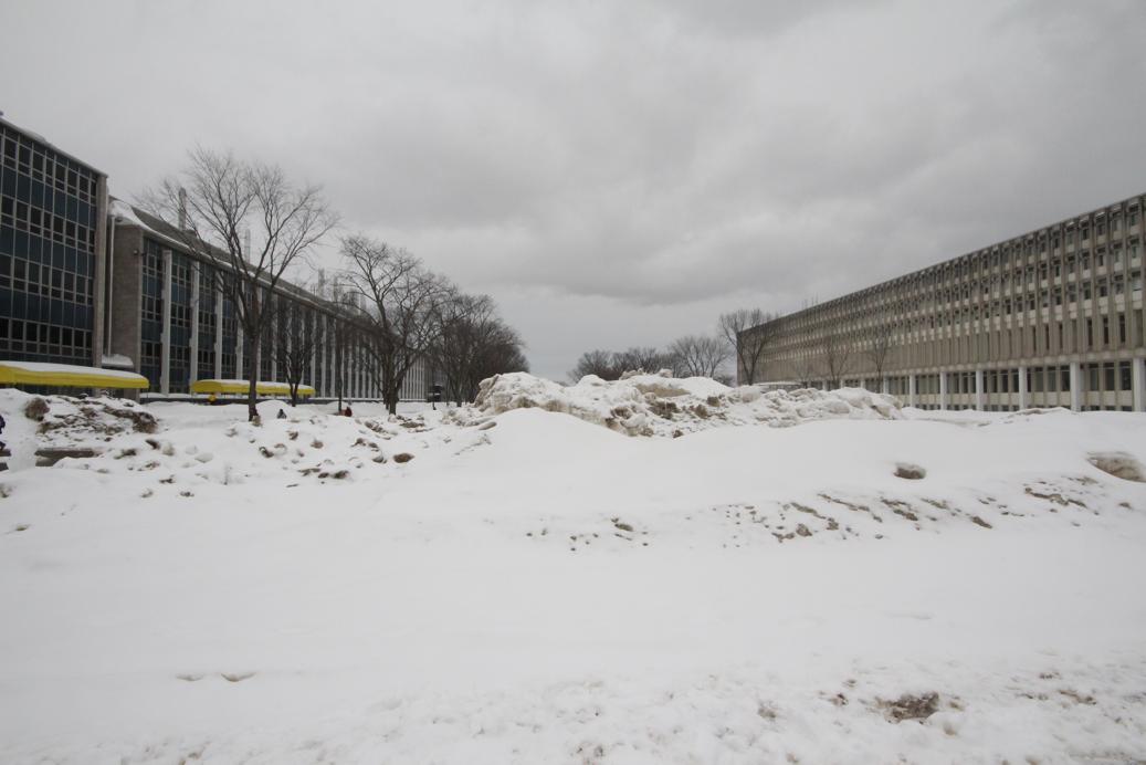
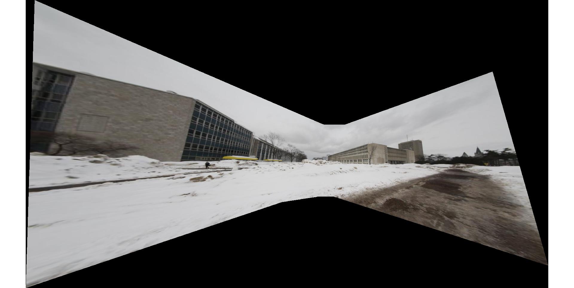
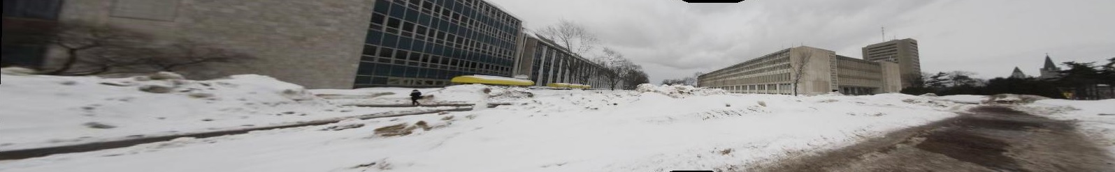
Following images are displayed as result relevant to first part :
 |  |  |  |  |
Manually Selected Points (10 points)
Manually Cropped
 |  |  |  |  |
Manually Selected Points (20 points)
Manually Cropped
 |  |  |  |
Manually Selected Points (15 points)
Manually Cropped
Part 2: Automatic matching
Once we built a program to calculate homography and stitch the image based on user's input, we want to fully automate this process. In order to achieve this, we used Harris corner detection to describe all the corners of an image. Then the amount of points were reduced by using adapative non-maximal suppression. This smaller subset of points was then used to extract descriptors and create matchings between descriptors using Lowe's comparison of epsilon. Since these points are automatically chosen, there might be some outliers which corrupts the homography. In order to avoid that, we use RANSAC, which stands for "RANdom SAmple Consensus". Basically, we randomly choose four points of samples several times and choose one that most points agree with that. Finally, we get the stable homography to project and stitch image as we did above.
In short,
· Choose photographs
· Corner detection (Harris)
· Adaptive Non-Maximal Suppression
· Feature Descriptor
· Feature matching
· Random Sample Consensus (RANSAC)
· Stitch two images together
Corner detection (Harris)
Harris corner detection using Harris matrix which use the first order derivitive .
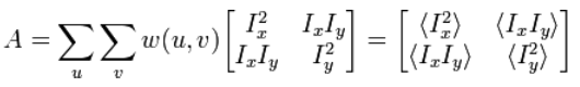
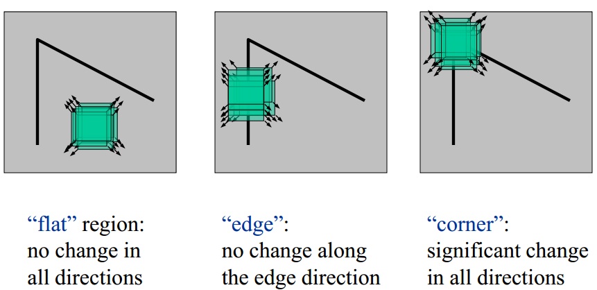
A corner (or in general an interest point) is characterized by a large variation of S in all directions of the vector (x, y). By analyzing the eigenvalues of A , this characterization can be expressed in the following way: A should have two "large" eigenvalues for an interest point, which is determined by:

Adaptive Non-Maximal Suppression
We first sort all the potential corner points, and then try all corners from the corner "intensity", restricted by the minimum radius between nearest respected corner points. This process is operated iteratively, by the decreasing "distance".
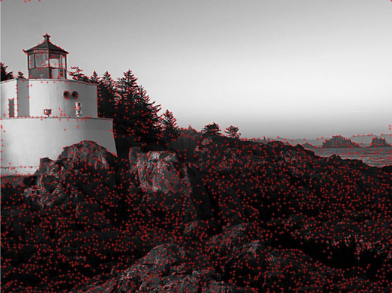
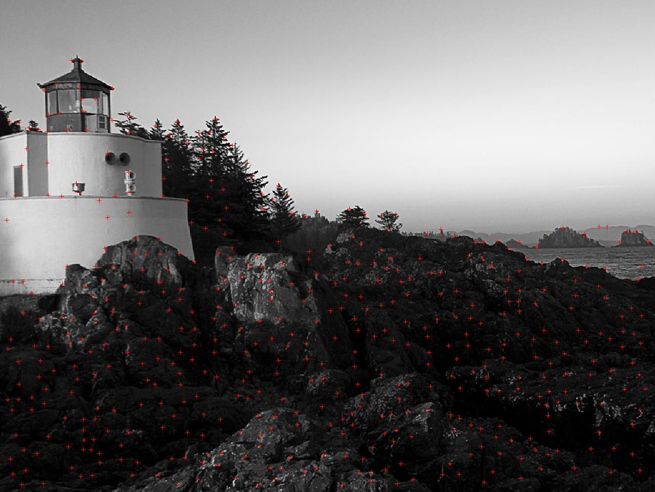
Harris Corner Detection Result Adaptive Non-Maximal Suppression Result
Feature points matching
This step is implemented using the method discribed in [ Lowe, 1999 ], calculating the error ratio between the first closest match and the second closest match. Here, I set the threshold to be 100.
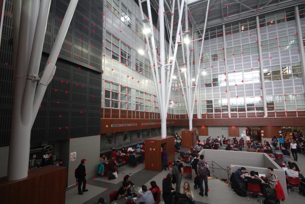
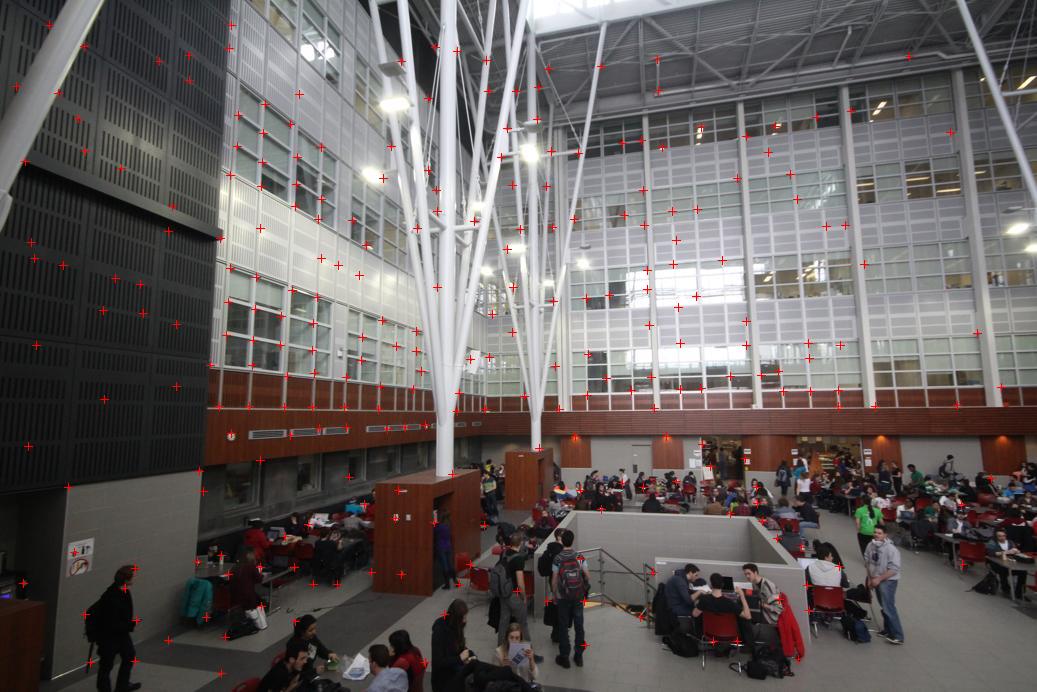
Base Image with Selected Features Input Image with Selected Features
Random Sample Consensus
In this step, we randomly choose some sample points as corresponding points, and count number of points which agree with this prespective transormation and called it num_of_Inliers. Finally, we return a homography matrix with the greatest number of inliers.
Hint :
(In the automatically stitching procedure, we always select the middle image as the reference image and divide the whole images to left and right side images. Then the Homography matrix is calculateed over each side seperately.)
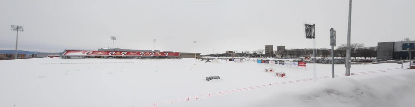
Following images are displayed as result relevant to second part :
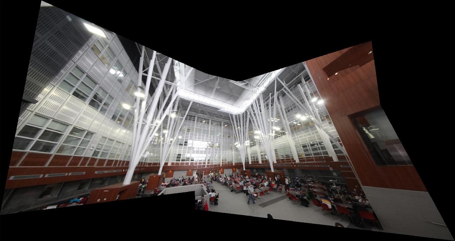
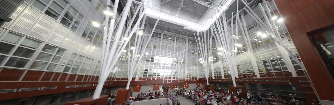
 |  |  |  |  |
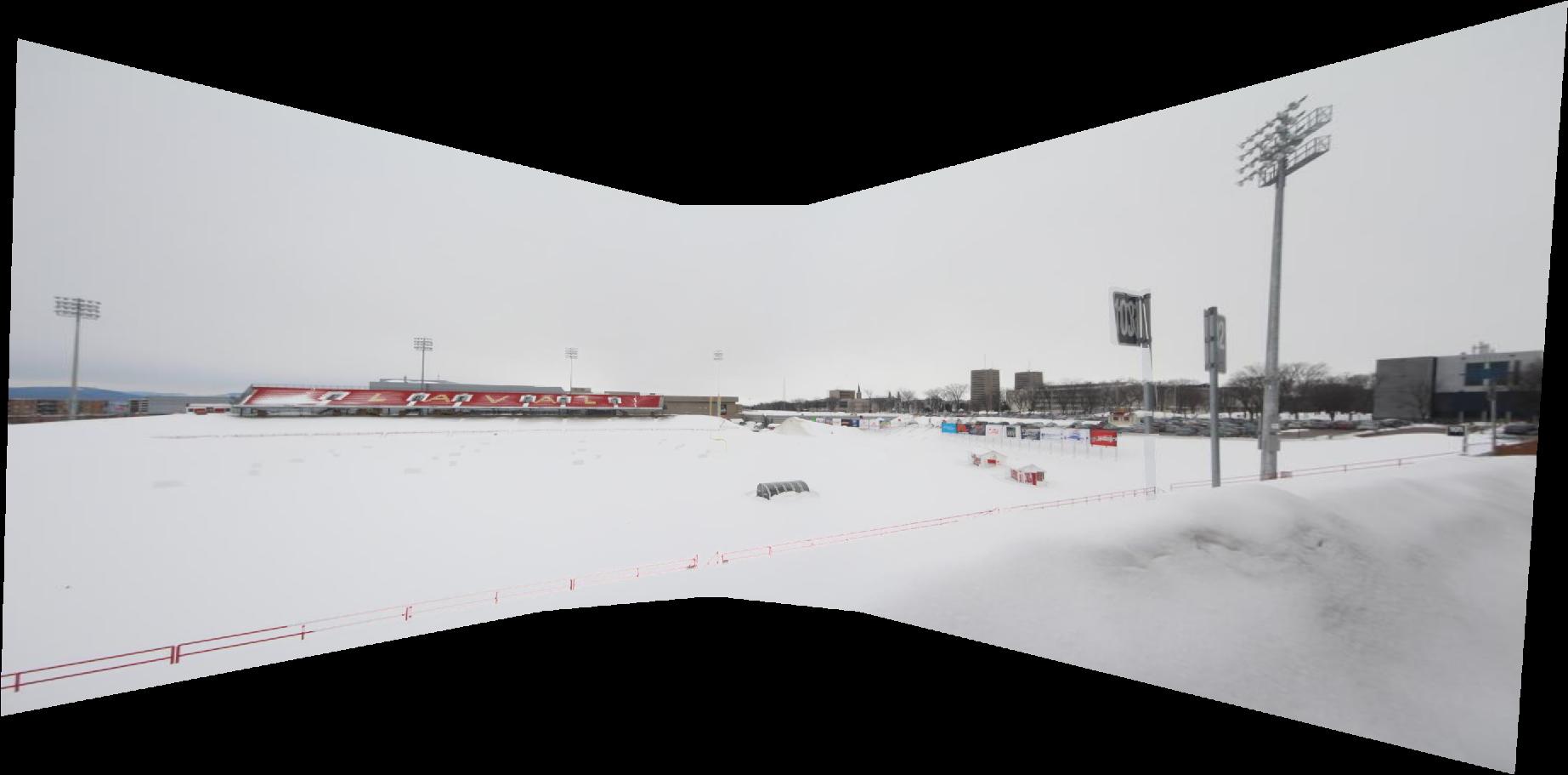
Automatic Image Stitching
Manually Cropped
 |  |  |  |
 |  |  |
Automatic Image Stitching
Manually Cropped
 |  |  |  |
Automatic Image Stitching
Manually Cropped
It seems that manual matching gives us better result than automatic selection, since the feature selection procedure may choose false features or the threshold of RANSAC process can not provide enough percision.
Part 3: Bells and Whistles
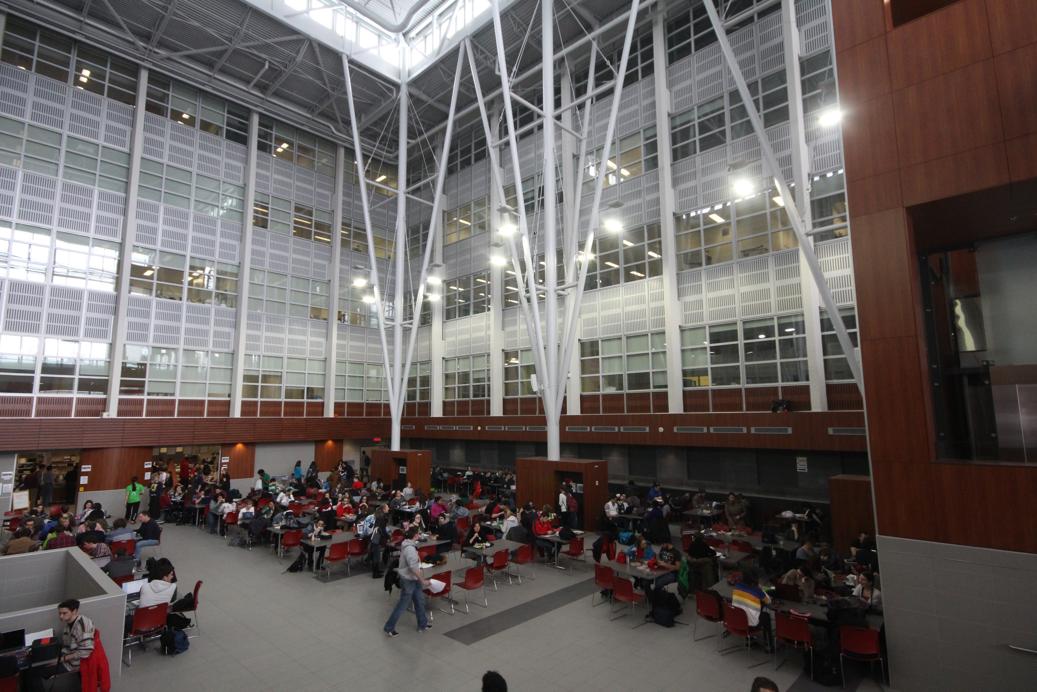
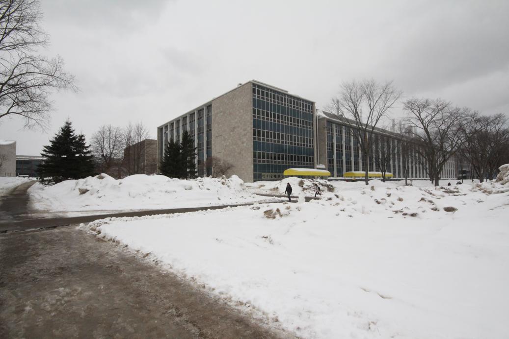
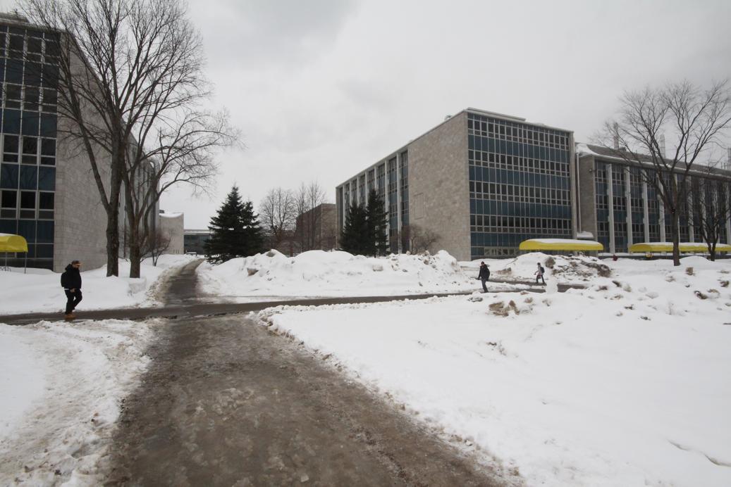
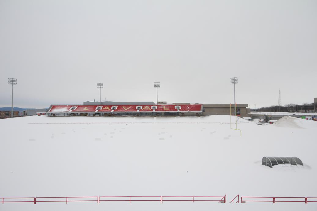
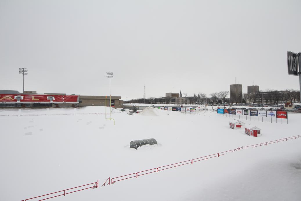
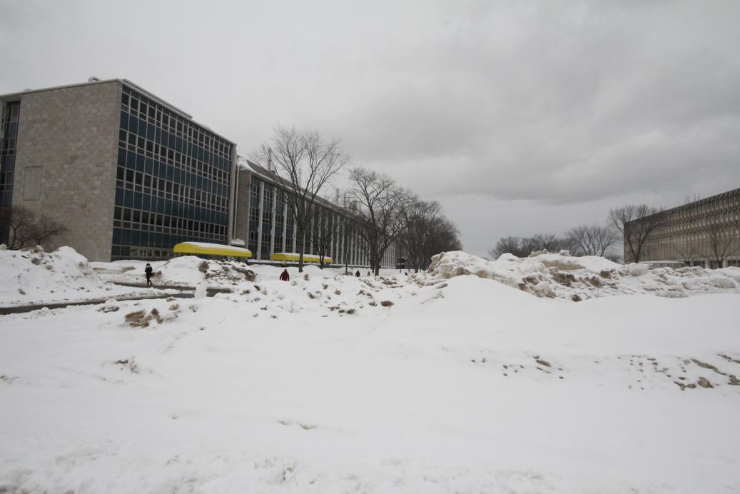
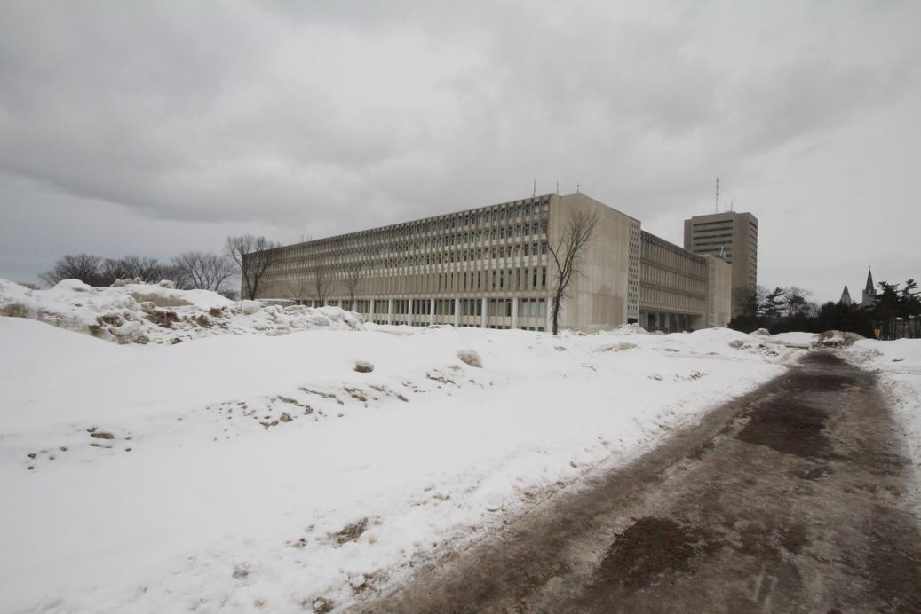
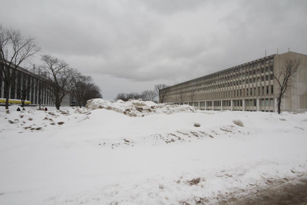
3-1 : Use my own images!
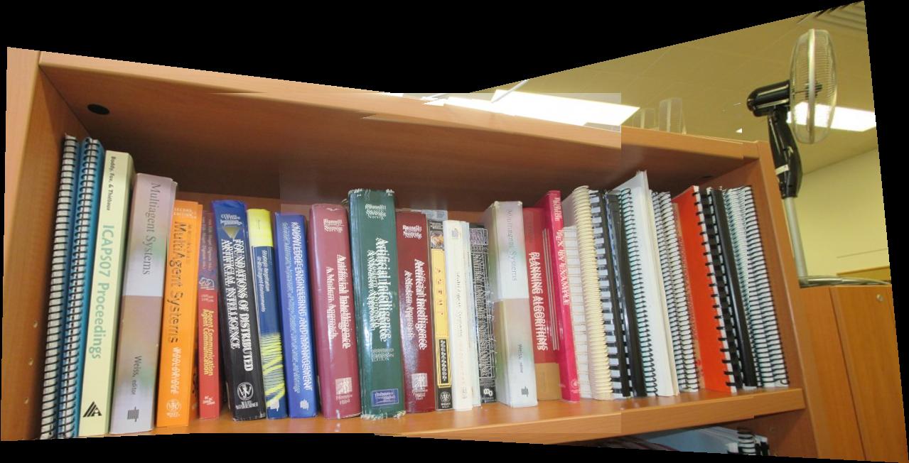
Automatic Image Stitching
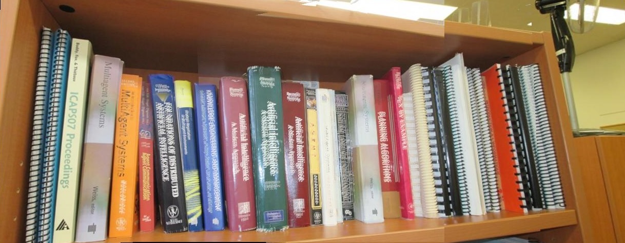
Manually Cropped
Automatic Image Stitching
Manually Cropped
Automatic Image Stitching (Image Source)
Manually Cropped
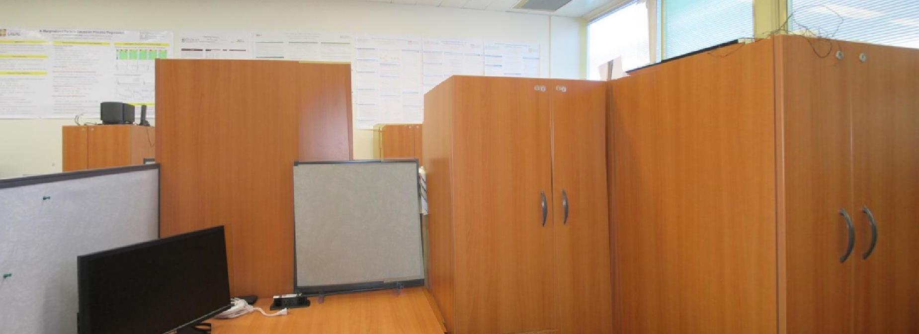
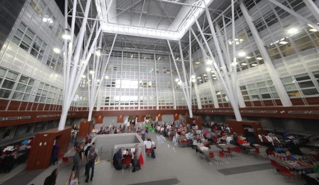
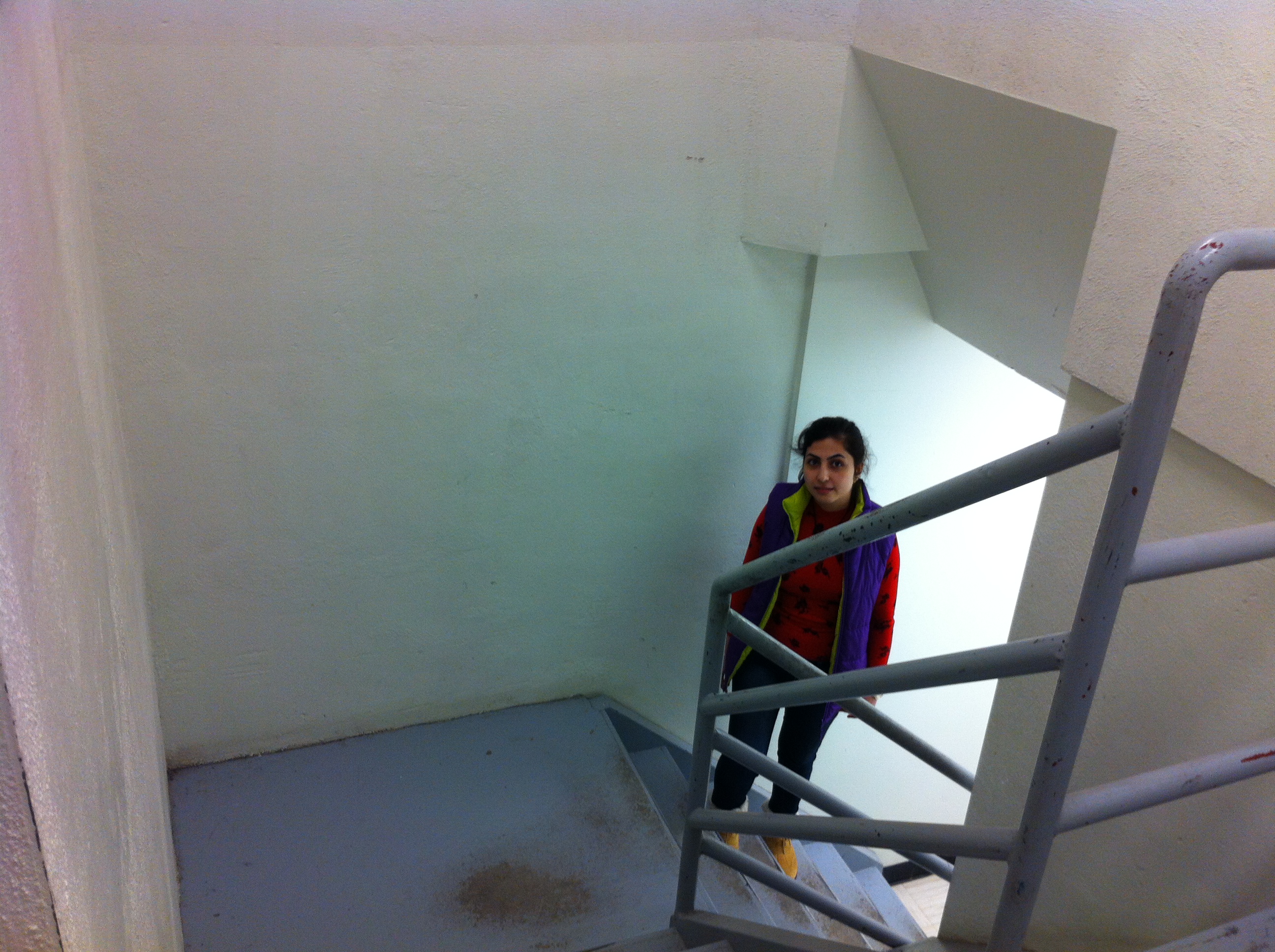
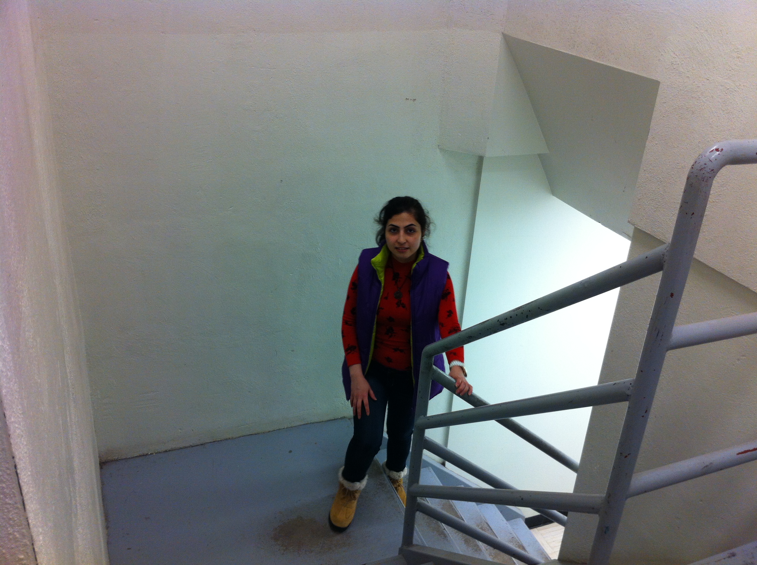
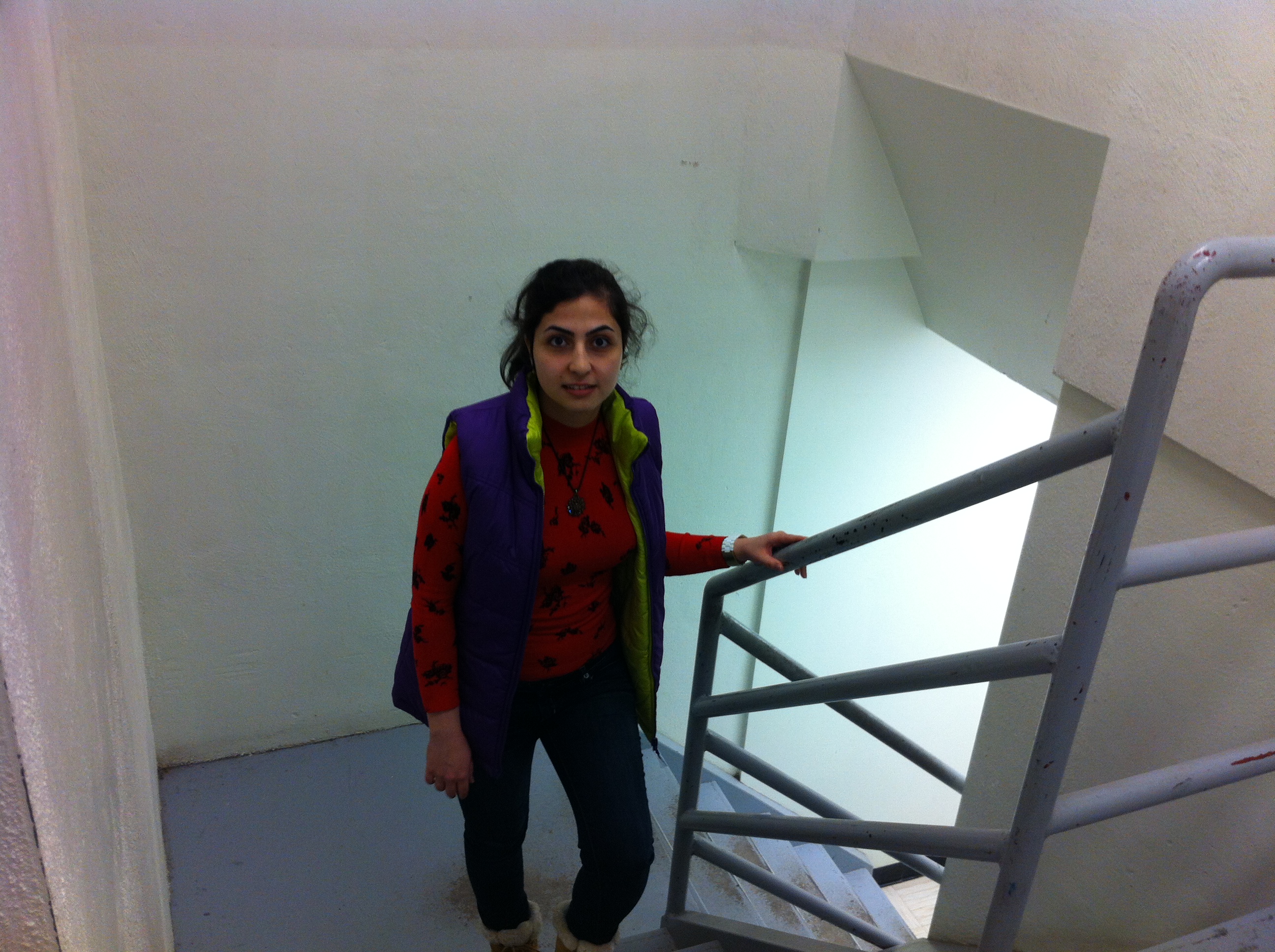
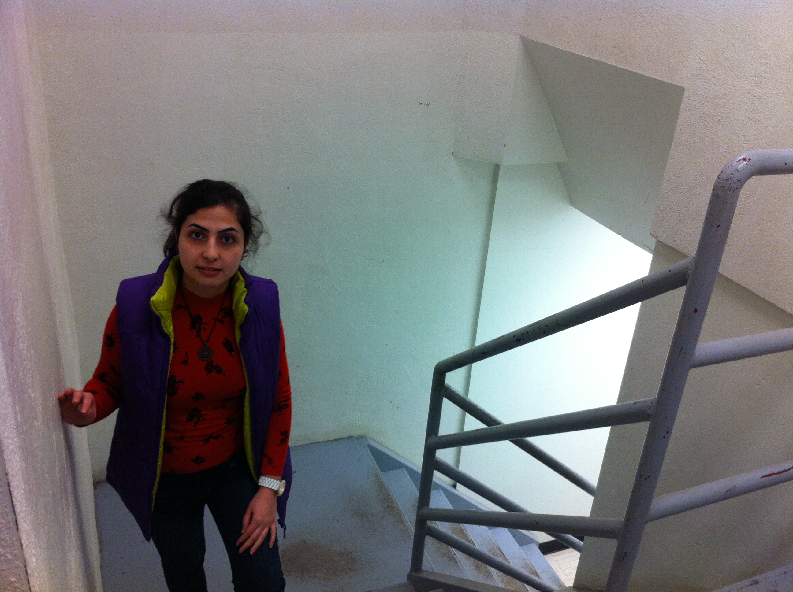
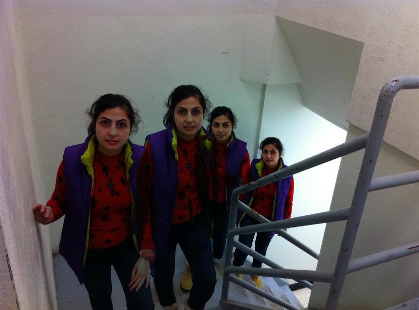
3-2 : Create an interesting/bizarre mosaic.
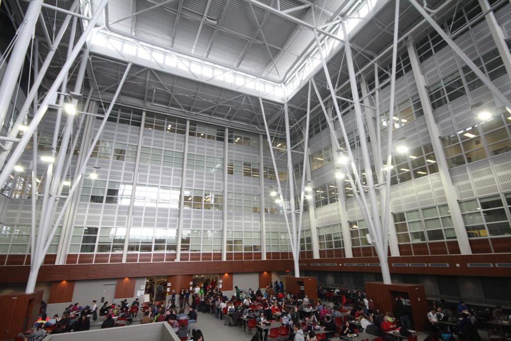
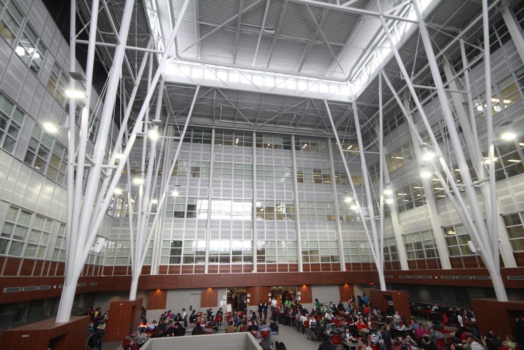
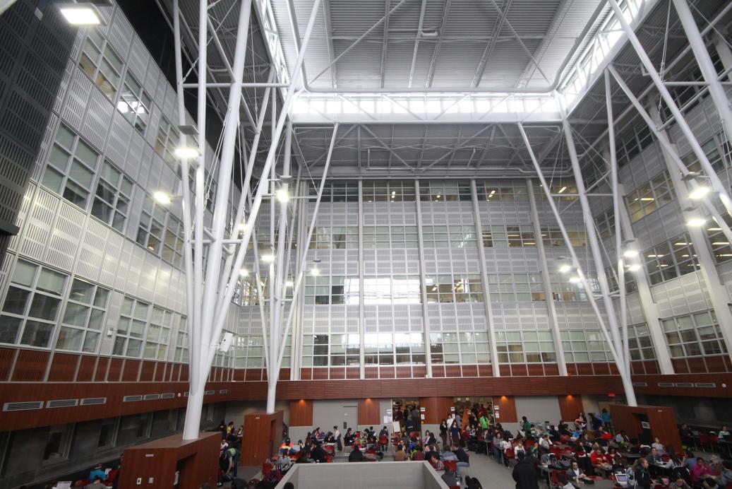
The camera was fixed, and as I moved around. My friend captured the images.
 |  |  |  |
 |
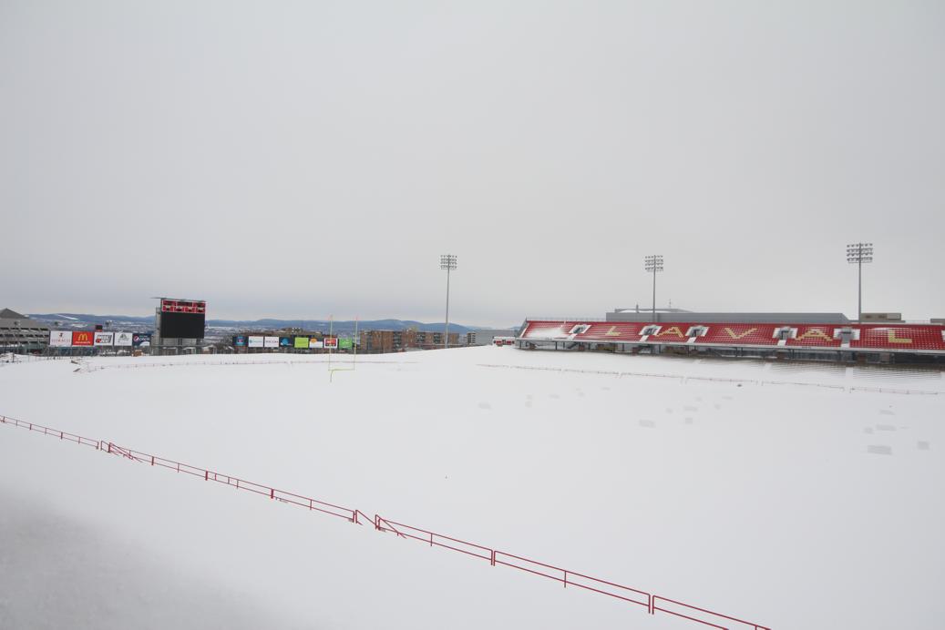
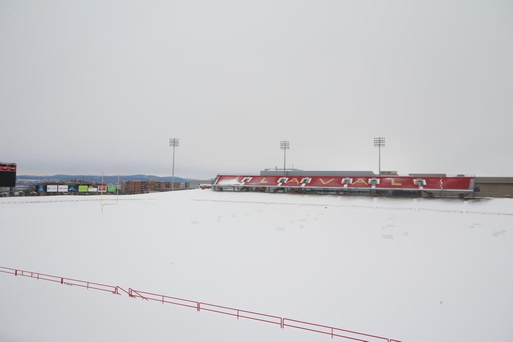
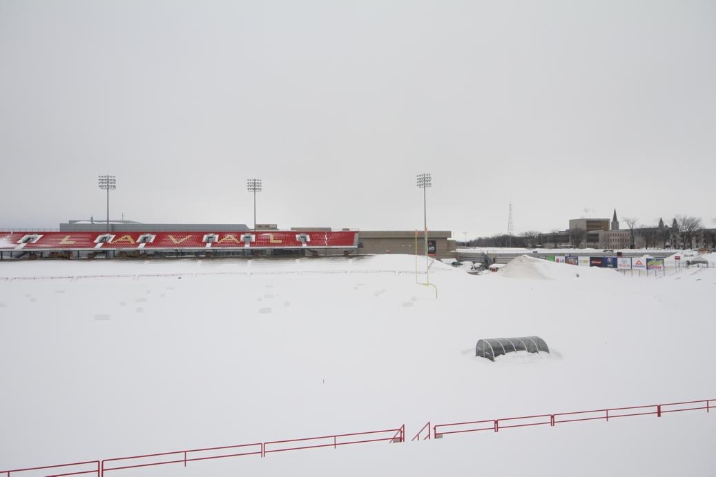
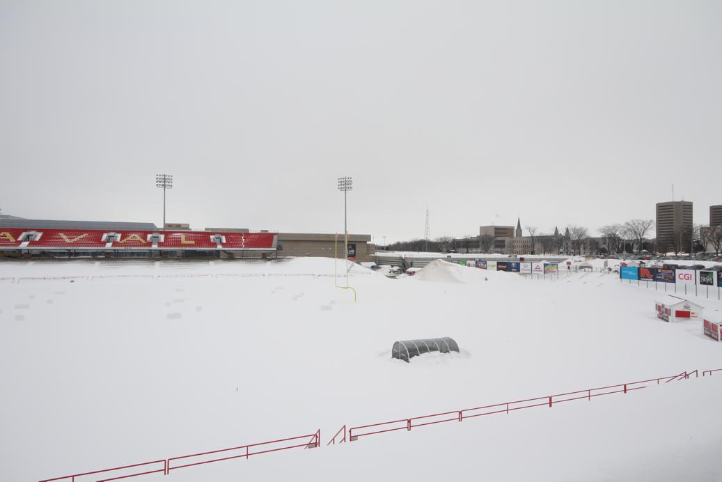
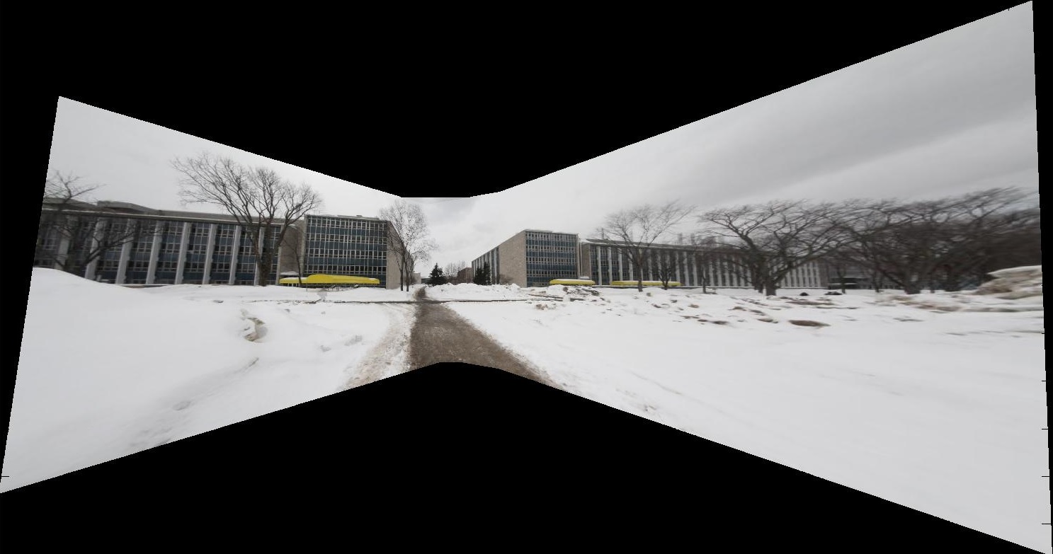
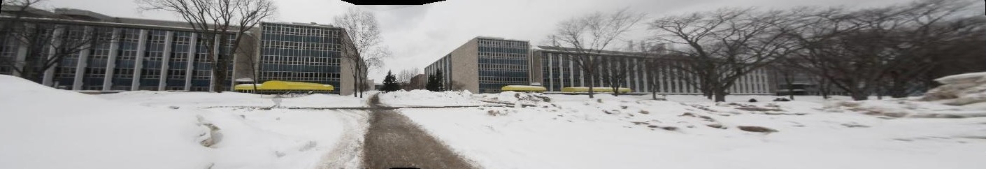
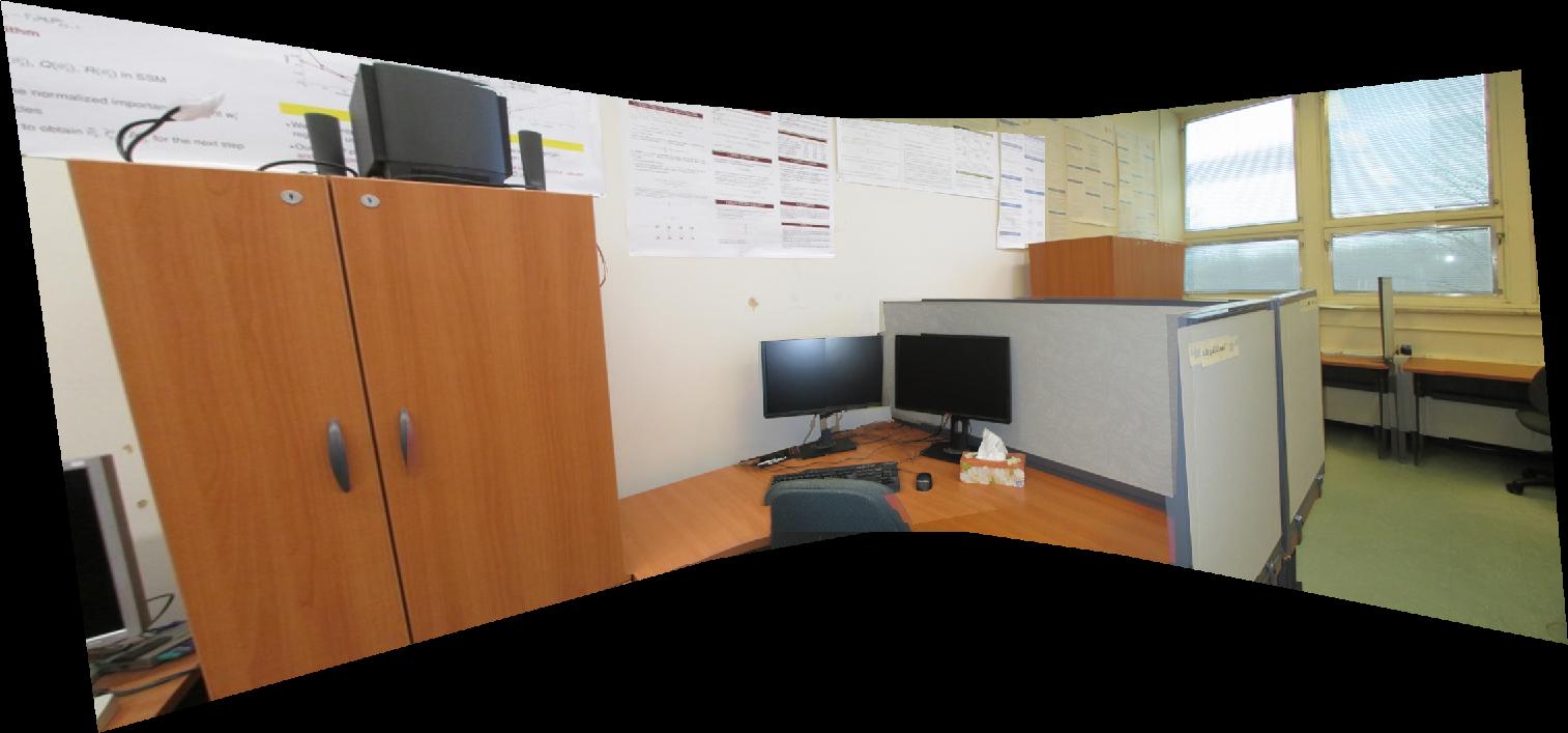
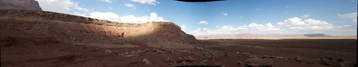
3-3 : 360-degrees cylindrical panorama
The advantage of a cylindrical panorama over a rectilinear panorama is that the former is capable of capturing a scene with 360 degree view. A rectilinear panorama fails at this task because homography will generate large warping as the number of images increases.
Making cylindrical panorama consists of five steps:
1. Calibrate a camera to find its focal length in pixels.(f = 1278.56 Pixel)
2. This information is used to compute the cylindrical projection later.
3. Map pixels from image coordinates to cylindrical coordinates by computing an approximate cylindrical projection.
4. Use feature detection to find a list of matching features, and compute the transformations between each pair.
5. Use RANSAC to select the best transformation, and apply that transformation to an image.
6. Composite the images.
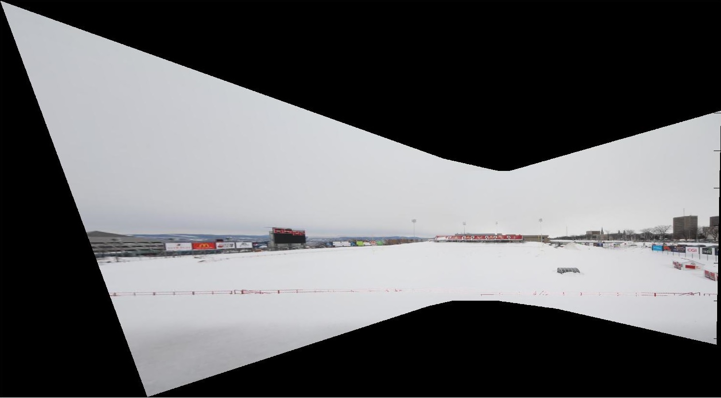
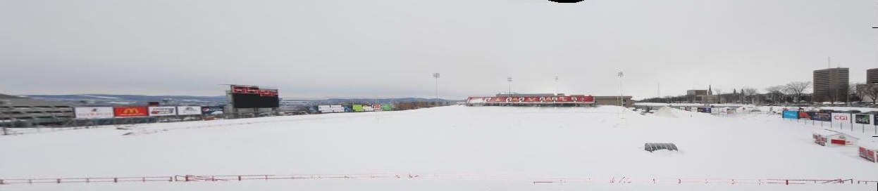
Cylindrical Projection :
We compute approximate cylindrical projection using focal length. By given the focal length f, image coordinates (x,y), the corresponding cylindrical coordinates (x', y') is:
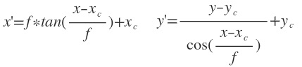
Note that in this notation, x is the width of the image and y is the height. Also we need to find the focal length in pixel value since both (x, y) and (x', y') are in pixels.
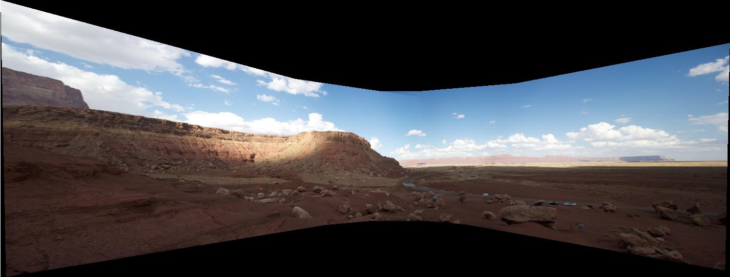
Here are the result of my work. I used all images of Panorama1 , while it was imposible to produce solely with rectilinear panorama. The result is not perfect since I did not have any information relevant to distorsion coefficients.
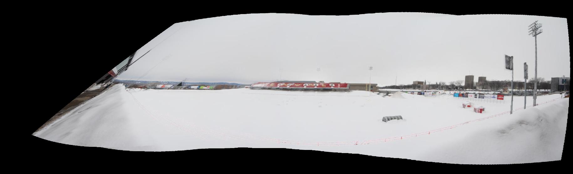
Cylindrical Panorama
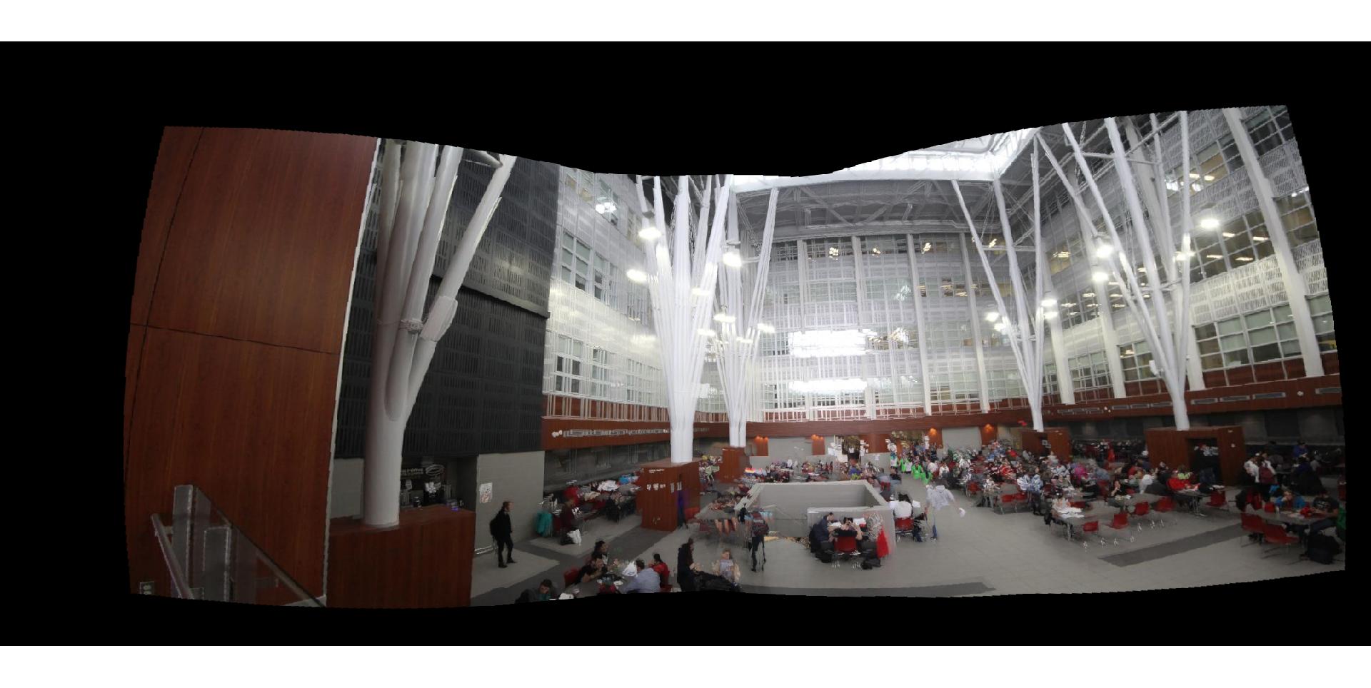
Cylindrical Panorama
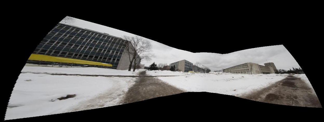
Cylindrical Panorama with 8 images
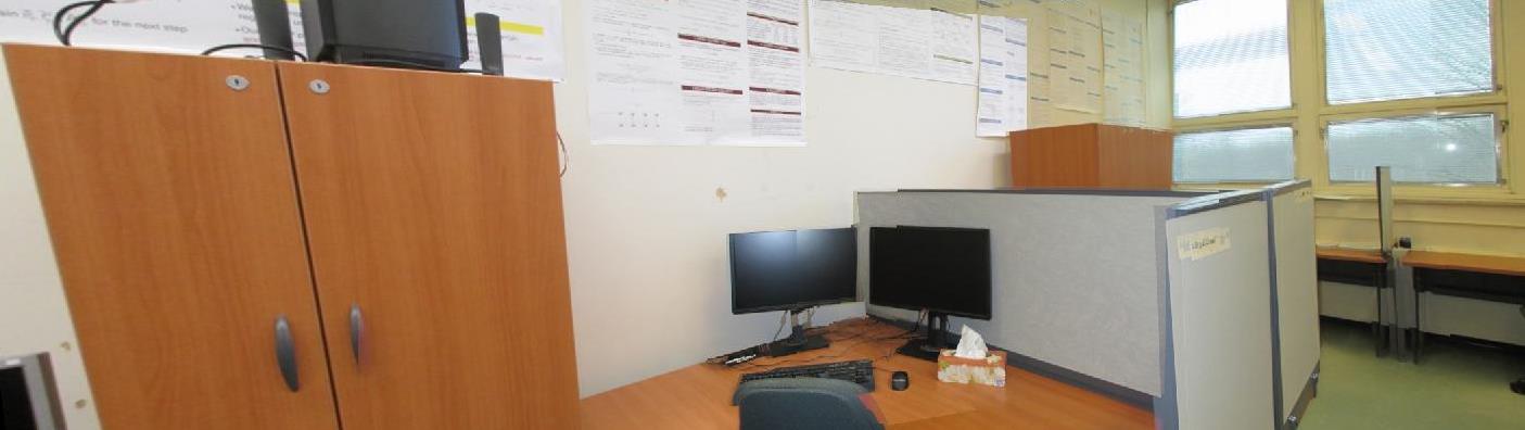
In bellow you can observe and compare the result of Cylindrical with Rectilinear panorama !
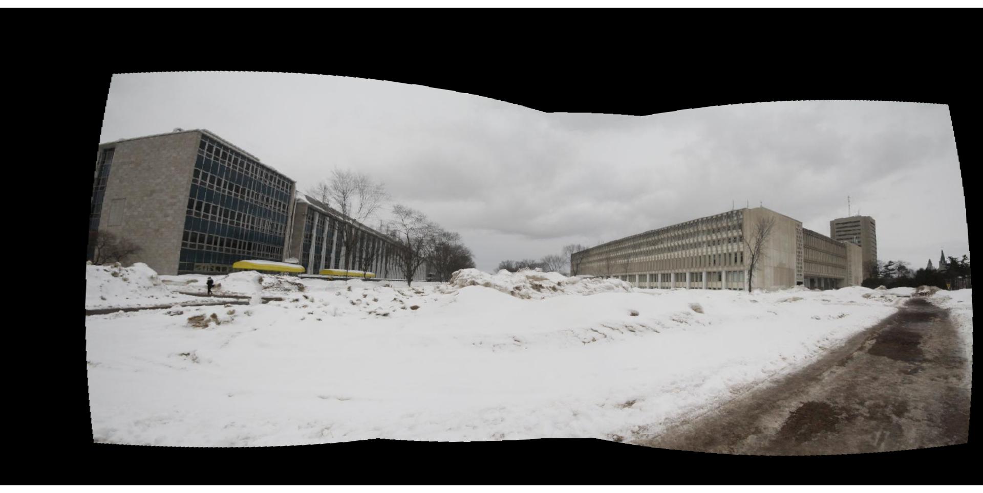
Cylindrical Panorama
Rectilinear panorama