Project Description
The objective of this final project is to implemnt the image quilting algorithm fro texture synthesis and texture transfer. The texture synthesis is the porcess of generating a large texture by selecting small patches from the sample texture and stitch them together. For texture transfer, the image is re-rendered using the texture sampled from the texture image.
Algorithm Inplementation
Part 1: Texture Synthesis
The construction of synthesised texture based on the idea of [Efros and Freeman 2001] can be done mainly in three ways. The naive one is to randomly select patches from a texture and put them together [see the code 'quilt_random.m']. A better solution is to sample the patches and lay them down in overlapping patterns such that the sampled patch has the relatively small SSD error with the previous (left or top) patches in the overlap region [see the code 'quilt_simple.m']. To alleviate the noticeable edge artifacts, the best solution is to find the minimum SSD path on the error surface of the overlap region by Seam Carving algorithm and treat this optimal path as the boundary of the overlap region [see the code 'quilt_cut.m'].
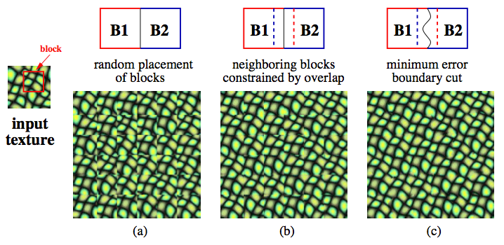 |
(1) To generate a large target texure image we iterate through it in raster scan order in steps of a patch size.
(2) For every location in the target image, we randomly sample a patch from the source texture image that overlaps with the previously selected patches within some error tolerance. Specifically, for each candidate patch from the source texture image we calculate the SSD error with previously selected patches on the overlap region, and then choose the patch with the minimum error.
(3) To reduce the noticeable edges, we find a minimum cut on the overlap region using dynamic programming. This is done by first finding the optimal patch through minimum SSD. Then we calculate the error surface between the previously chosen patches and the optimal patch on the overlap region. Finally, the minimum error path on the error surface found by seam carving algorithm is used as the boundary of the new patch
Result of Texture Synthesis
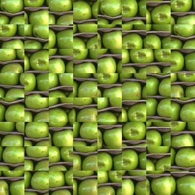
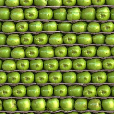
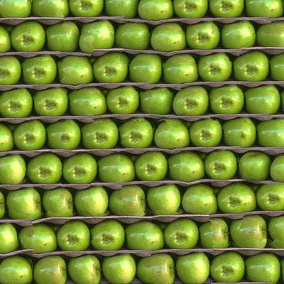
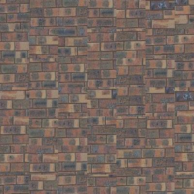
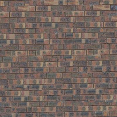
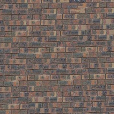
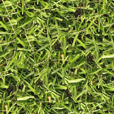
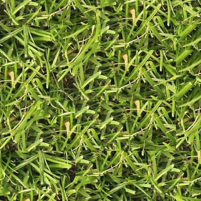
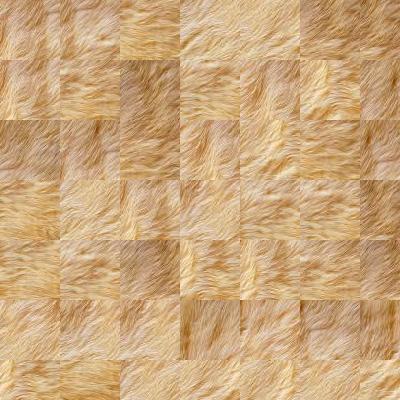
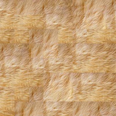
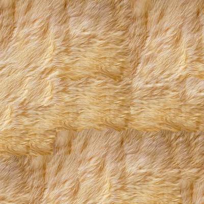
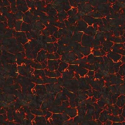
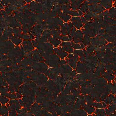
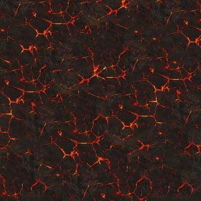
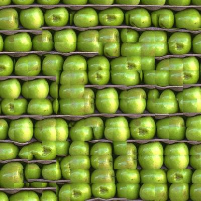
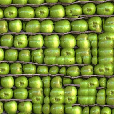
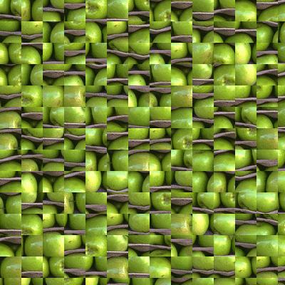
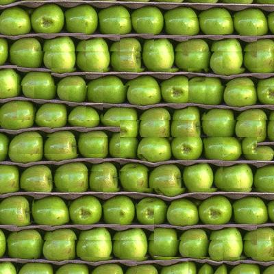
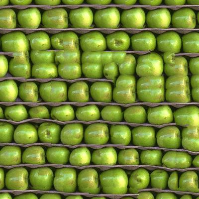
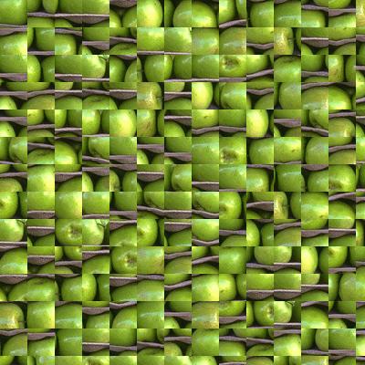
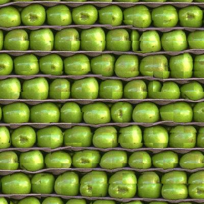
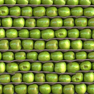
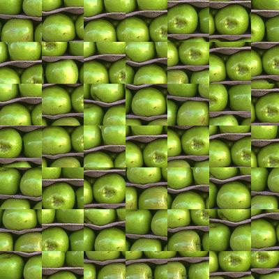
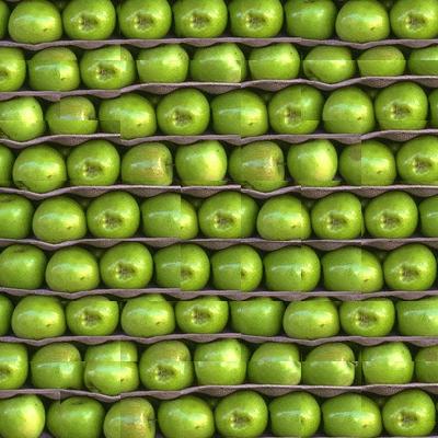
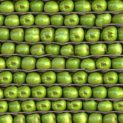
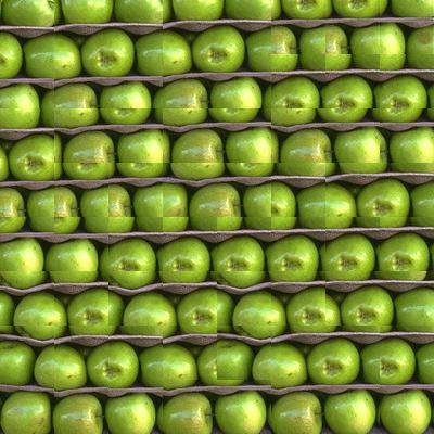
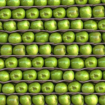
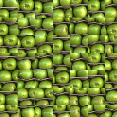
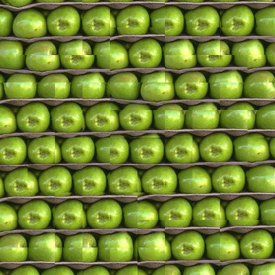
The image on the left shows the result of the naive method, where the randomly selected patches are placed side by side. The image on the middle corresponds to the method by choosing the patch with minimum SSD on the overlap region. The rightmost image illustrates the result of lowest SSD with minimum cut.
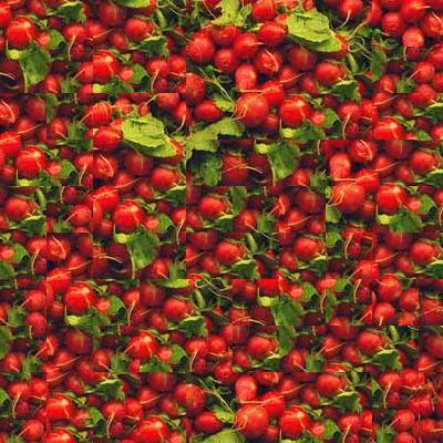
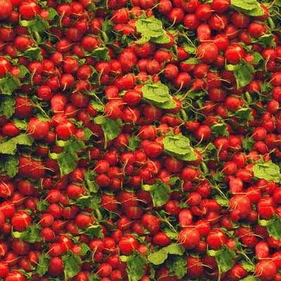
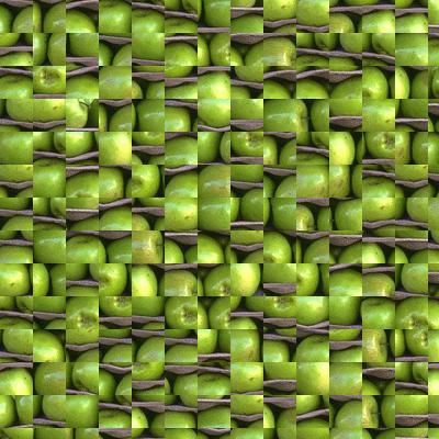
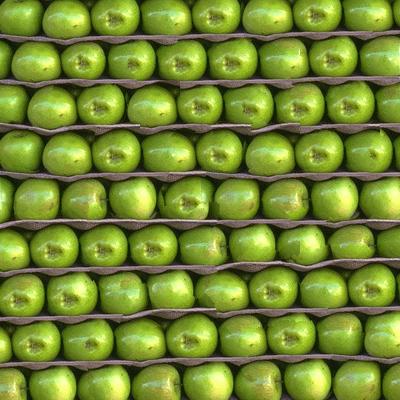
Taking the following 'apples' texture image as an example, we can see that the result of the random method is not so good as the best SSD which looks more natural than the left one. However, the noticeable edges on the overlapping regions can still be observed in the middle image. To fix this problem, the rightmost image applying minimum cut shows the best result with less edge artifacts. The patch size we choose is 50 and the overlap is set to be 1/6 of patch size.
| random | best SSD | best SSD + minimum cut |
 |
 |
 |
 |
 |
 |
 |
 |
 |
 |
 |
 |
 |
 |
 |
 |
 |
 |
 |
 |
 |
 |
 |
 |
 |
 |
 |
 |
 |
 |
 |
 |
 |
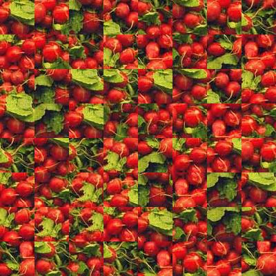
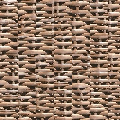
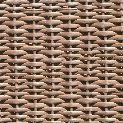
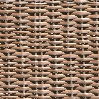
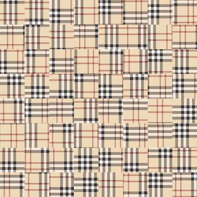
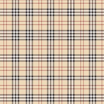
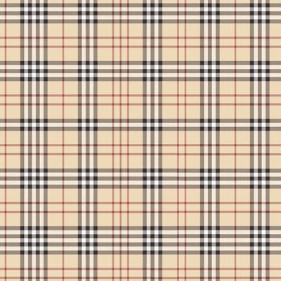
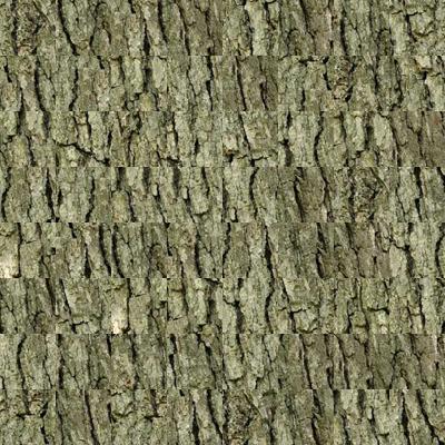
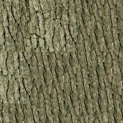
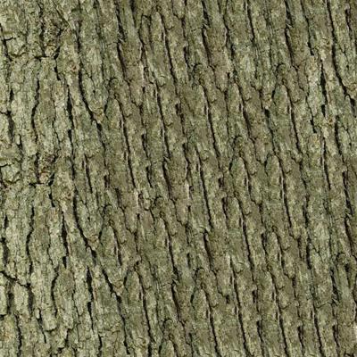
From the above results, we can observe that the best SSD method performs much better than the random method for all cases, and the minimum cut method is in turn better than the best SSD. For the strict structured image like 'plaid', the best SSD and minimum cut are almost perfect, we can not see any artifacts edges. In the case of semi-structured image like 'bark' and 'fur', which is harder than the structured case, the result is still good.
It is interesting to compare the results with different patch size and overlap size and to see how the different sizes affect the performance. To do this, we first set the patch size to be 30 with overlap size 2 in the first row, 5 in the second row and 10 in the third row, respectively. The results are shown in the following images. When the patch size is the same, the larger overlap size corresponds to the better results, which is obvious in the first row agianst the third row of minimum cut method. However, the smaller patch size and large overlap size will take more time to generate the result.
| random (path size = 30) | best SSD (path size = 30) | best SSD + minimum cut (path size = 30) |
 |
 |
 |
 |
 |
 |
 |
 |
 |
Next, we set the patch size to be 60 with overlap size 5 in the first row, 10 in the second row and 20 in the third row, respectively. The results are illustrated as below. It is clear to see the larger patch size has a better result when the overlap sizes are equal. (see the second row in the '30' group vs. the first row in the '60' group, overlap size is 5).
| random (path size = 60) | best SSD (path size = 60) | best SSD + minimum cut (path size = 60) |
 |
 |
 |
 |
 |
 |
 |
 |
 |
Part 2: Texture Transfer
In this part, we implement texture transfer that is based on the idea of texture synthesis algorithm [see the code 'texture_transfer.m']. Different from the texture synthesis algorithm, the optimal patch we sampled from the source texture image should respect the two following constraints at the same time:
(1) the sampled patch has small SSD match error with previously selected patches on the overlap region.
(2) the sampled patch has small correspondence error with the target image at the desired position.
To accommodate this additional error term, the total error in the texture synthesis algorithm can be modified as a weighted sum between the overlap error and the correspondence error:
total_error = alpha * overlap_error + (1 - alpha) * correspondence_error
where 'overlap_error' is the SSD distance between the optimal patch and previous synthesized patch on the overlap region. And the 'correspondence_error' is the SSD distance between the optimal patch and the patch from the target image at the desired position. The alpha balances the texture synthesis and the fidelity to the target image correspondence map. The correspondence map is the intensity image in this implementation.
Result of Texture Transfer
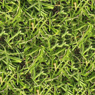
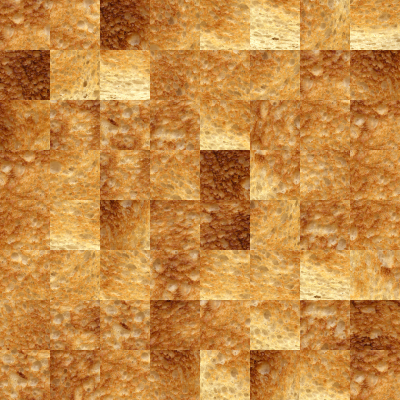
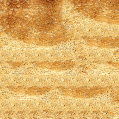
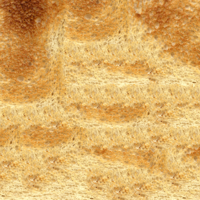
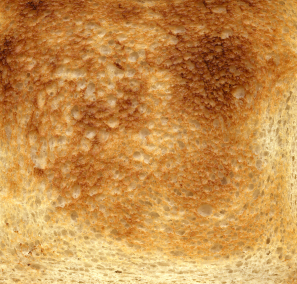
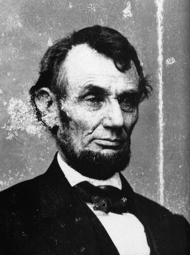
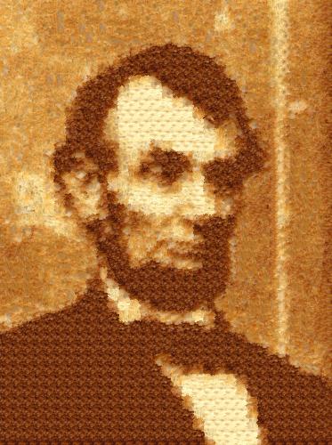
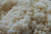
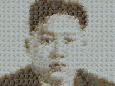
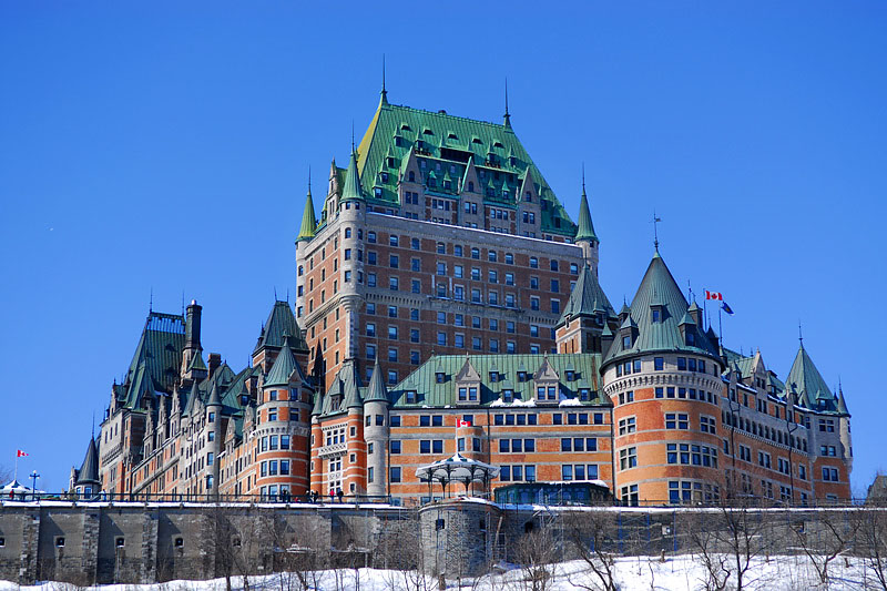
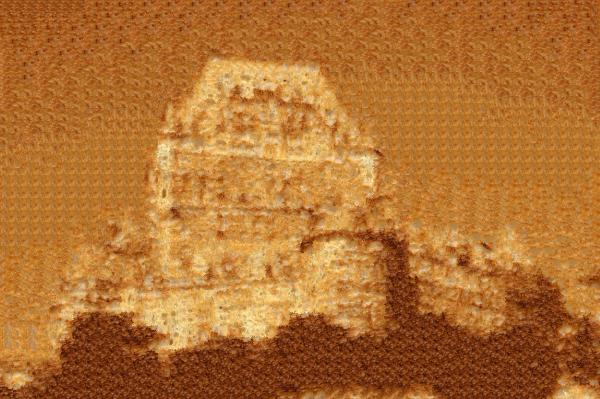
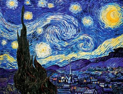
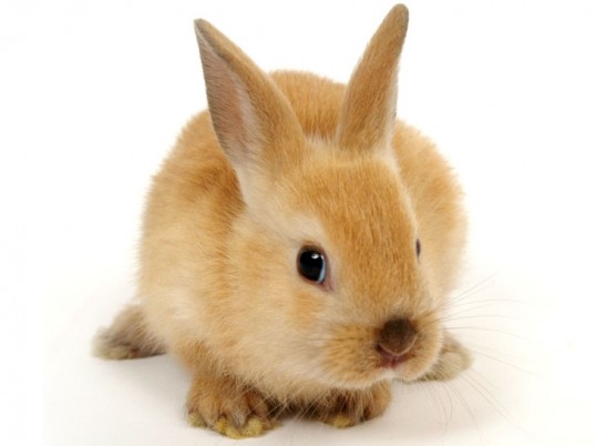
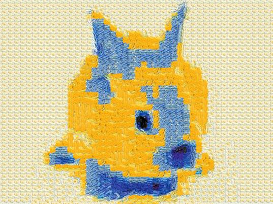
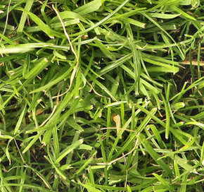
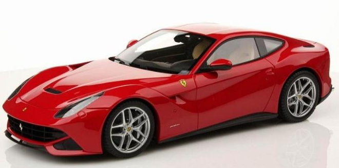
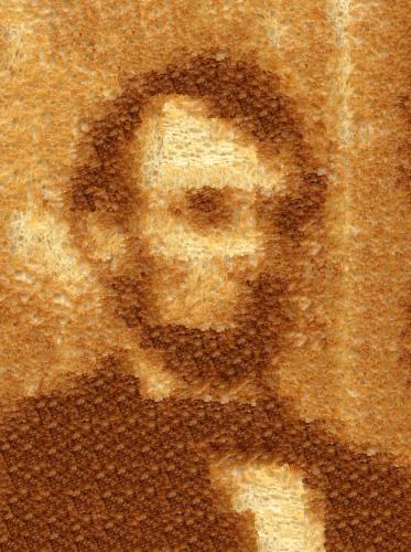
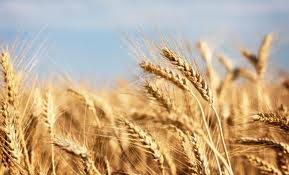
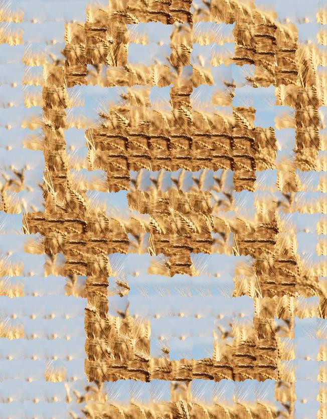
On the left is the source texture image, and the target image is shown in the middle, the resulting transfered image is illustrated on the right.
| the source texture image | the target image | the synthesized image |
 |
 |
 |
 |
 |
 |
|
 |
 |
 |
 |
 |
 |
 |
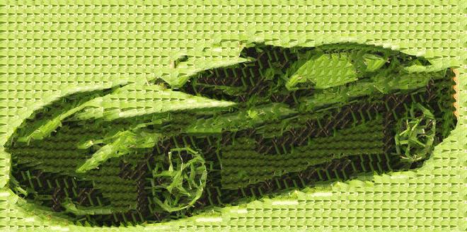 |
As we can see from the above results, the algorithm works well for all the examples, especially for the toast texture image. This is because the method requires that both the source texture image and the target image have a good distribution of intensity. Thus, we can sample patch with any level intensity from the source texture image, otherwise there is not enough variation and a lot of textures will be repeated in the resulting image. For instance, the rice texture iamge has less variation than the toast texture image, and the resulting 'lincoln + toast' image looks much smoother and better than the 'kim jong un + rice' image.
Bells and Whistles
(1) Iterative Texture Transfer
In this part, we implement the iterative texture transfer scheme suggested in the paper so as to produce a visually pleasing results [see the code 'texture_transfer.m']. Specifically, we iterate over the generated image several times, decreasing the patch size with each iteration. During each iteration, the optimal patch not only has the best SSD error with the neighbour patches on the overlap region, but also has the lowest SSD error with whatever was synthesized at the current patch from last iteration. Therefore, the total error becomes:
total_error = alpha * (overlap_error + previous_synthesized_error) + (1 - alpha) * correspondence_error
where the 'previous_synthesized_error' is the SSD error between current patch and the patch from last iteration at same position. In order to achieve a better performance, we should iterate 3 to 5 times and ajust the alpha according to the formula:
alpha = 0.8 * (current_iteration - 1) / (total_iteration_number - 1) + 0.1
Result of Iterative Texture Transfer
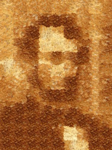
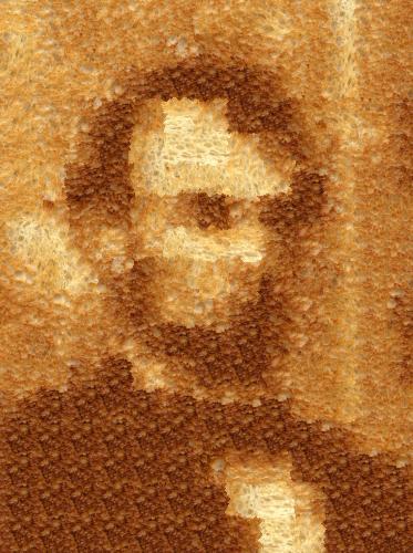
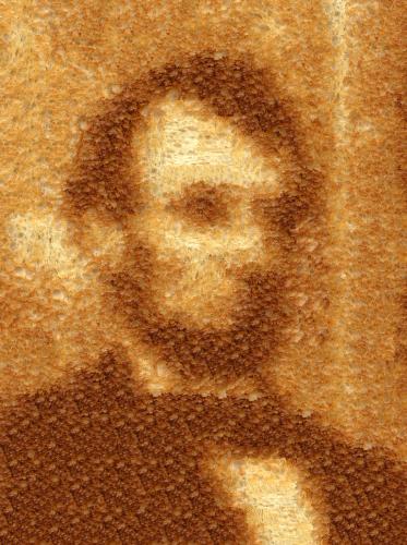
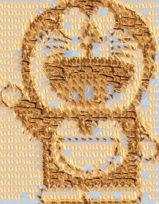
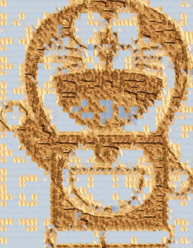
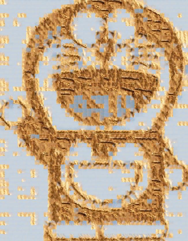
The following results are obtained with 4 iterations, and the initial patch size is 50 for the 'lincoln', 'doraemon' example and 40 for the 'jobs' example.
| 1st iteration | 2nd iteration | 3rd iteration | 4th iteration |
 |
 |
 |
 |
| the source texture image | the target image |
 |
 |
| 1st iteration | 2nd iteration | 3rd iteration | 4th iteration | |||||||||||||||||||||||||
 |
 |
 |
 |
|||||||||||||||||||||||||
| the source texture image | the target image |
 |
 |
| 1st iteration | 2nd iteration | 3rd iteration | 4th iteration |
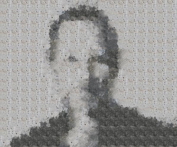 |
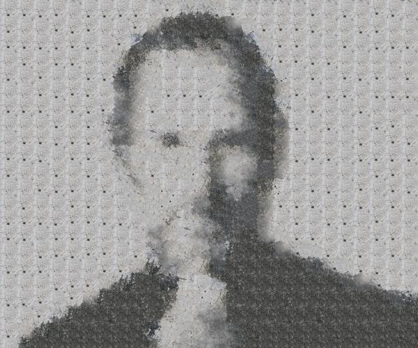 |
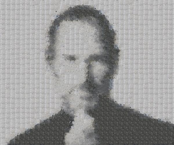 |
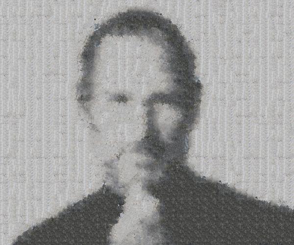 |
As can be seen from the above results, the quality of the synthesized image has been improved as the iteration number increases for all cases. On one hand, the patch size is decreased at each iteration, thus the details of the target image can be rendered because of the smaller patch samples, but the quality of texture tends to be degraded. On the other hand, as alpha is increased at each iteration, the correspondence match between the sampled patch and target image becomes less important while the correspondence match with the neighbouring patches becomes more significant, this tends to attach more importance to the texture quality, which makes the synthesized image look more natural. By adding a extra 'previous_synthesized_error' to first part of the total error term, the content of previously synthesized image can be preserved, and quality of representation of target image can also be guaranteed. This iterative scheme is all about keeping the balance betweeen quality of texture and the accuracy of the rendering of the target image. For instance, at the 4th iteration of the 'lincoln' example, the synthesized image reveals more details than the prevous iterations while trying to keep the stitched patches as natural as possible.
(2) Region Filling and Object Removal by Exemplar-Based Image Inpainting
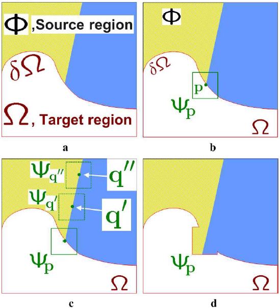 |
In this part, I implement the full version of exemplar-based image inpainting method from [Criminisi et al. 2004]. Generally speaking, the objective of this algorithm is to fill the hole in or remove the large objects from the original photograph, and replace them with visually plausible backgrounds. This procedure is illustrated in the figure above. Specifically, it can be done by repeating the following steps: [see the code 'inpaint.m']
(1a) Identify the fill front 'delta_omega'.
(1b) Compute the priorities of patch 'sai_p'. The priority computation consists of two parts: the first part 'C_p' is called confidence term which is a measure of the amount of reliable information surrounding the pixel 'p', while the second part 'D_p' is called data term measuring the strength of isophotes hitting the front 'delta_omega'.
(2a) Find the patch 'sai_p' on the fill front with the maximum priority.
(2b) Find the exemplar patch 'sai_q' that minimizes the SSD error with the selected patch 'sai_p'.
(2c) Copy the image data from the exemplar patch 'sai_q' to the patch 'sai_p' on the fill front.
(3) Update the fill front 'delta_omega', as well as the confidence term 'C_p' and isophote in data term 'D_p' along the fill front.
Result of Exemplar-Based Image Inpainting
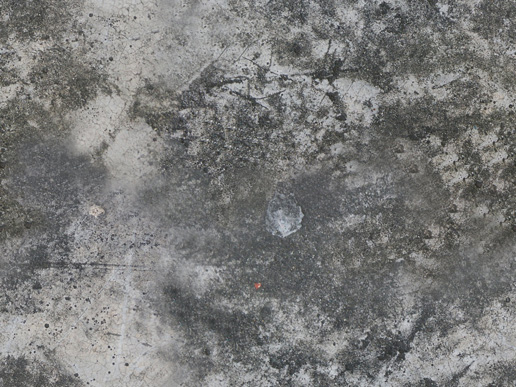
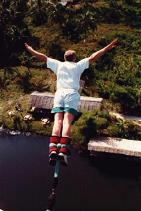
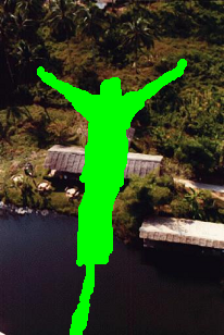
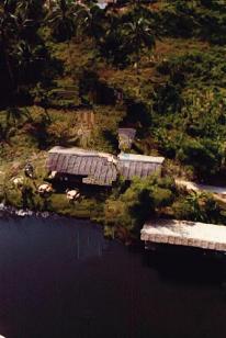
The images below are the original image and the fill region mask.
| the original image | the fill region |
 |
 |
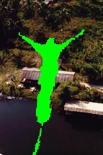
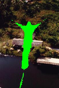
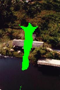
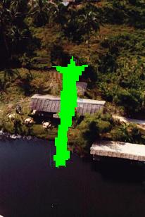
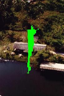
The following examples demonstrate the intermediate results of the algorithm
 |
 |
 |
 |
 |
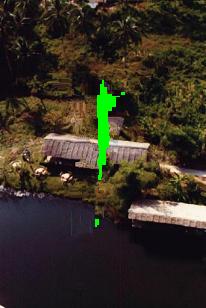 |
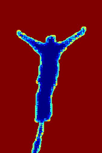
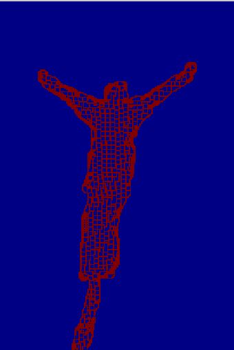
The image on the left is the final result. The images on the middle and right correspond to the confidence term clolrmap and data term colormap respectively.
| the final result | the confidence term | the data term |
 |
 |
 |
As we can see that the result is reasonably well, and the colormap of the confidence term shows that the priority is high where there is a out-pointing corner.